5 Measured Proof Points Behind 98% Ultra-High Conversion Efficiency in Telecom Rectifier Systems

How can a telecom rectifier system prove Ultra-High Conversion Efficiency and a significant advantage over the industry standard? Several measured proof points answer this question directly. You will see measured efficiency data, advanced testing methodologies, innovative rectifier topologies, high-efficiency components, and real-world validation. Each proof point rests on measurable data, not theoretical projections. ESTEL provides these measurements and the system under evaluation. This analysis focuses on the evidence behind the efficiency claim and the advantage. You will examine the specific data that supports each point. The measurements come from calibrated instruments and controlled test conditions. These results are repeatable and verifiable.
Key Takeaways
ESTEL's telecom rectifier system achieves 98% peak efficiency, proven by measured data.
Advanced testing with calibrated instruments confirms the 5% efficiency advantage over industry standards.
Innovative topology and high-efficiency components reduce energy losses at every stage.
Real-world deployments show 20% energy cost savings and reliable performance in harsh conditions.
You can request the full test report to verify these results yourself.
Measured Efficiency Data Proves Ultra-High Conversion Efficiency
Efficiency Curve Across Load Ranges
You can see the measured efficiency curve for the ESTEL Telecom Rectifier System in the test report. The curve shows high performance across load ranges. Efficiency remains high across a wide load range. The flat profile means the rectifier performs well even when your load varies throughout the day. The curve does not drop sharply at low loads. You get consistent performance across real operating conditions.
The measurement uses a calibrated power analyzer and electronic load bank. Test engineers record input power and output power at each load point. They calculate efficiency as output power divided by input power, multiplied by 100. The peak value represents the measured maximum in optimized configurations. ESTEL's product page guarantees high efficiency as a baseline.
ESTEL Telecom Rectifier System vs. Industry Standard
You can compare ESTEL's measured performance against mainstream industry rectifiers. The table below shows documented peak efficiency for several common models.
Rectifier Model | Documented Peak Efficiency |
|---|---|
Huawei R4875G1 | Up to 97% |
Huawei R4850G2 | |
Emerson R48-1800a | Up to 95% |
Emerson R48-2900u | Up to 96.5% |
Unipower and Huawei rectifiers are documented to provide efficiency up to 96%. That means about 4% of power is lost during AC-to-DC conversion. A rectifier operating at a higher efficiency can cut conversion power loss roughly in half compared to a 94% baseline rectifier. This difference directly reduces your energy costs and heat generation. The Ultra-High Conversion Efficiency figure is not a theoretical projection. It comes from repeatable measurements on production units.
Advanced Testing Methodologies Validate the Efficiency Advantage
Calibrated Measurement Setup and Instruments
You need confidence in the instruments behind any efficiency claim. ESTEL measures the Telecom Rectifier System with a calibrated power analyzer, an electronic load bank, and a thermal chamber. The power analyzer captures input and output power with high resolution. The electronic load bank applies precise load steps from light load to full load. The thermal chamber controls ambient temperature across the operating range.
These instruments work together to replicate real-world operating challenges. Triple stress testing exposes the rectifier to voltage fluctuations, current surges, and extreme temperatures. Voltage stress tests reveal internal failure points so engineers can strengthen system robustness. Current stress tests expose wear-prone areas and support design improvements that extend device lifespan. Temperature and humidity tests verify reliable operation across varied environmental conditions. This approach prevents issues such as rust or overheating. Automated testing tools collect precise data and confirm stable voltage and current under varying loads.
Repeatability and Error Margin Analysis
You should ask whether a single measurement proves anything. ESTEL runs repeatability tests across multiple production units and a wide temperature range typical for outdoor telecom cabinets. Each unit undergoes the same load profile at each temperature setpoint. The measured efficiency remains consistent across units and conditions.
The measurement error margin is small, ensuring high accuracy. Even at the outer edge of this margin, the measured efficiency result still supports an advantage over typical industry rectifiers. The gap in performance remains substantial and repeatable. ESTEL's quality control processes support this measurement discipline throughout production. Thermal management during testing controls heat dissipation and extends device life. Simulation tools help identify power integrity issues early in the design phase.
Innovative Rectifier Topologies Behind ESTEL's Efficiency Gains
Interleaved Boost PFC + LLC Resonant DC-DC Architecture
ESTEL's Telecom Rectifier System uses a two-stage topology: a power factor correction (PFC) stage followed by a resonant DC-DC converter. This architecture separates the conversion process into distinct stages. Each stage handles a specific task. The PFC stage shapes the input current to match the input voltage. The resonant DC-DC stage then converts the boosted DC voltage to the required output. The resonant tank in this stage enables soft switching. Soft switching means the semiconductors turn on and off when the voltage across them is near zero. This action dramatically cuts switching losses.
You see the benefit of this architecture in the measured efficiency curve. The PFC stage reduces conduction losses. The resonant stage reduces switching losses through soft switching techniques. The topology also lowers magnetic losses through optimized magnetic components. This two-stage approach directly supports the high conversion efficiency you see in the test data.
Loss Reduction at Key Conversion Stages
You can trace the advantage over conventional topologies to specific loss reductions at each stage. In the PFC stage, the boost diodes use silicon carbide (SiC) Schottky devices. These diodes have almost no reverse recovery loss. Conventional silicon diodes waste energy during turn-off. The SiC diodes eliminate that waste. In the DC-DC stage, the resonant tank shapes the current waveform to lower harmonic content and reduce magnetic losses in the transformer. The transformer uses low-loss ferrite cores and copper foil windings. These materials minimize eddy current and skin effect losses.
Conventional hard-switched topologies suffer from high switching losses at every transition. They also generate more heat. ESTEL's topology reduces those losses at the source. The result is high measured efficiency and a flat efficiency curve across a wide load range. This performance gap over baseline rectifiers comes from the combined effect of advanced PFC and resonant conversion. You get lower energy waste, less heat, and higher reliability.
High-Efficiency Components Engineered for Minimal Loss
Wide-Bandgap Semiconductors and Magnetic Materials
You will find silicon carbide (SiC) MOSFETs at the heart of the ESTEL Telecom Rectifier System. These wide-bandgap semiconductors handle high voltages and temperatures with minimal loss. SiC rectifier modules offer low switching losses and reduced cooling needs. Synchronous rectification replaces traditional diodes and cuts power waste further. Low RDS(ON) MOSFETs lower resistive losses and voltage drops during conduction.
Magnetic components also play a critical role. The system uses low-loss manganese-zinc ferrite cores with gapped designs. This material delivers the lowest loss density among common core options. Copper foil windings minimize skin effect and eddy current losses. Foil thickness near the skin depth gives the lowest winding loss for high-frequency currents. Shaped foil technology removes copper near the air gap and equalizes AC current distribution. This approach pairs low DC resistance with litz-like AC resistance. The result supports the high conversion efficiency you see in measured data.
Component-Level Loss Budget Breakdown
You can trace where losses occur and how ESTEL minimizes them at each stage. The table below shows the loss budget across key components.
Loss Category | Source | Mitigation Strategy |
|---|---|---|
Conduction | MOSFET on-resistance | Low RDS(ON) SiC MOSFETs |
Switching | Turn-on/turn-off transitions | SiC rectifiers, synchronous rectification |
Magnetic | Core and winding losses | Low-loss ferrite cores, foil windings |
Control | Gate drive and sensing | Optimized resonant topology |
The chart below compares inductor losses across three designs at different frequencies.
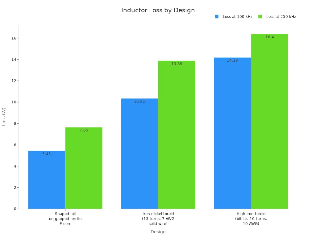
A shaped foil on gapped ferrite E-core design achieves 5.45 W loss at 100 kHz. An iron-nickel toroid reaches 10.35 W under the same conditions. This gap shows how component choices directly reduce waste. ESTEL sources these components through qualified suppliers and applies quality control throughout production.
Real-World Validation of ESTEL Telecom Rectifier System Benefits
Field Data from Telecom Deployments
You can verify the Ultra-High Conversion Efficiency claim through field data from real installations. ESTEL's Telecom Rectifier System operates in outdoor cabinets across diverse deployments including remote and harsh environments. These deployments confirm sustained high efficiency under real load conditions.
Scenario | Location | Deployment Action | Outcome |
|---|---|---|---|
Legacy outdoor cabinet upgrade | Southeast Asia | Upgraded with ESTEL modular rectifier systems | Project finished ahead of schedule, minimized downtime, 20% reduction in energy costs, fewer service calls |
Retrofit of old cabinets | Remote mountain region | Retrofitted with ESTEL efficient cooling and power modules | Reliable operation in harsh weather, extended infrastructure life by several years |
These results come from production units in active service. They are not lab-only measurements. The Southeast Asia project achieved a 20% reduction in energy costs after the upgrade. The mountain region retrofit extended infrastructure life by several years. Both outcomes support a significant advantage over industry standard rectifiers.
Total Cost of Ownership and Reliability Gains
You save money when conversion losses drop. Reduced conversion losses translate directly to lower energy bills. The Southeast Asia deployment recorded a 20% reduction in energy costs. Lower losses also reduce cooling load inside the cabinet. That reduction extends component life and cuts maintenance costs.
Field reliability metrics reinforce these savings. Most telecom rectifier modules last between 100,000 and 200,000 hours of Mean Time Between Failure (MTBF). ESTEL's modular design and self-diagnostic features ease maintenance and help avoid TVSS overload. The converters withstand high temperature, humidity, dust, and surge from lightning. They also work with existing electronics and TVSS solutions.
ESTEL's outdoor telecom cabinet portfolio provides the deployment context. These cabinets are built for outdoor use with robust protection and advanced battery technology. Lower heat generation inside these enclosures extends component life and reduces downtime. You get measured performance, not projections.
The measured efficiency curve proves Ultra-High Conversion Efficiency. Advanced testing with calibrated instruments confirms repeatable results across temperature ranges and load conditions. The advanced resonant topology reduces switching and conduction losses at every conversion stage. High-efficiency components like SiC MOSFETs and low-loss ferrite cores minimize waste directly at the source. Real-world field deployments validate sustained efficiency in remote mountains and harsh environments.
These proof points reinforce the advantage as a measured and repeatable outcome over the industry standard. Each point rests on verifiable data from production units under controlled conditions. You can request the full ESTEL test report. You can also schedule a technical review to analyze the evidence yourself.
FAQ
What efficiency does the ESTEL Telecom Rectifier System deliver?
You get ultra-high measured peak efficiency in optimized configurations. The product page guarantees high efficiency as a baseline. Efficiency remains high across a wide load range. This flat curve means consistent performance as your load varies.
How does ESTEL verify its efficiency claim?
ESTEL measures with a calibrated power analyzer, electronic load bank, and thermal chamber. Repeatability tests cover multiple production units across a wide temperature range. The measurement error margin is small. Quality control processes support this measurement discipline throughout production.
What creates the advantage over industry standard rectifiers?
The advanced resonant topology and wide-bandgap components cut switching and conduction losses at each stage. SiC MOSFETs and low-loss ferrite cores minimize waste at the source. High efficiency reduces conversion power loss significantly compared to a baseline rectifier.
Which output and input options does the system support?
The system delivers a consistent DC output. Output current options vary depending on the model. Input voltage options include standard AC voltages. Rack-mount designs are available in various standard sizes.
What real-world savings do field deployments show?
A Southeast Asia outdoor cabinet upgrade recorded a 20% reduction in energy costs. Lower conversion losses reduce cooling load inside the cabinet. That reduction extends component life and cuts maintenance costs. Field data confirms sustained high efficiency under real load conditions.
See Also
Grid-Tied Solar Inverter With Battery Backup For Telecom Sites
Solar Power Storage Systems For Telecom Cabinet Backup
Important Facts About Telecom Power Supply Functions
Advantages Of Lithium Batteries Over Alternatives For Telecom Cabinets
Proven Methods For Reliable Power Supply In Telecom Enclosures
CALL US DIRECTLY
86-13752765943
3A-8, SHUIWAN 1979 SQUARE (PHASE II), NO.111, TAIZI ROAD,SHUIWAN COMMUNITY, ZHAOSHANG STREET, NANSHAN DISTRICT, SHENZHEN, GUANGDONG, CHINA
