Deconstructing Core Components of a Telecom Rectifier System
A Telecom Rectifier System consists of several essential components that work together to ensure stable power delivery. These core parts include the power input module, transformer, rectification unit, filters, regulators, control and monitoring devices, safety features, output distribution, and cooling systems. Understanding each component helps maintain reliable telecom operations. ESTEL stands as a trusted provider, offering advanced and efficient solutions for telecom power needs.
Key Takeaways
Telecom rectifier systems convert AC power to stable DC power, ensuring reliable operation for telecom equipment.
Modular designs allow for easy expansion and maintenance, reducing downtime and supporting network growth.
Effective voltage regulation and filtering protect sensitive devices from fluctuations, enhancing system reliability.
Advanced monitoring features provide real-time data, enabling quick responses to issues and maintaining stable operations.
Robust safety mechanisms, including fuses and surge protection, safeguard telecom infrastructure from electrical faults.
Telecom Rectifier System Overview
Key Functions and Importance
A Telecom Rectifier System plays a vital role in modern telecom infrastructure. It converts alternating current (AC) from the utility grid into direct current (DC), which telecom equipment requires for stable operation. This conversion ensures that base stations, mobile networks, and data centers receive uninterrupted power. The system also regulates the DC voltage, usually maintaining it at a standard 48V DC, which matches the needs of most telecom devices.
Telecom networks depend on a reliable power supply to operate continuously, especially during power outages or fluctuations. The rectifier system supports this by providing backup battery charging, so networks remain active even when the main power fails. Its modular design allows for hot-swappable operation, which means technicians can replace or upgrade modules without shutting down the system. This feature ensures continuous power delivery and reduces downtime.
Key functions of a telecom rectifier system include:
Converting AC electricity to DC electricity for telecom equipment.
Regulating DC voltage to a stable level.
Charging backup batteries to maintain network operation during outages.
Ensuring a stable and reliable power supply for critical communication systems.
ESTEL’s System Features
ESTEL’s Telecom Rectifier System stands out due to its high efficiency, modular design, and adaptability. The system achieves efficiency ratings above 91%, which minimizes energy loss and reduces heat generation. This high efficiency leads to lower cooling requirements and energy cost savings. The modular architecture allows for flexible expansion, so operators can scale their power systems as network demands grow.
Description | |
|---|---|
90% to 92% | Standard models balance cost and performance. |
92% to 94% | High-efficiency models save energy. |
95% and Above | Ultra-efficient models save costs for large setups. |
ESTEL designs its rectifier systems to comply with international standards, ensuring safety and reliability. The systems meet certifications such as NEBS Level 3, CSA/UL, VDE, GR-3108, and CE Mark for Low Voltage Directive. These standards guarantee that the equipment performs well in harsh environments and meets global telecom requirements.
By focusing on quality, efficiency, and compliance, ESTEL provides telecom operators with dependable solutions that support continuous network operation and long-term infrastructure growth.
Power Input Module
Input Conditioning
The power input module acts as the first line of defense in a telecom rectifier system. It receives electrical power from the utility grid or an external generator. This module prepares the incoming power for further processing. Input conditioning involves filtering out electrical noise and stabilizing voltage levels. These steps protect sensitive telecom equipment from sudden spikes or drops in power.
Technicians often find that input conditioning uses components such as surge suppressors, electromagnetic interference (EMI) filters, and circuit breakers. Surge suppressors absorb voltage spikes caused by lightning or grid switching. EMI filters remove unwanted electrical noise that can disrupt communication signals. Circuit breakers provide a safety mechanism by disconnecting the system during dangerous overloads.
Proper input conditioning extends the lifespan of telecom equipment and reduces the risk of unexpected failures. Reliable input modules help maintain uninterrupted service, which is critical for telecom operators.
Voltage Adaptability
Telecom rectifier systems must operate in diverse environments. Power grids in different regions supply electricity at varying voltages. Some areas provide 220V, while others use 380V or even wider ranges. The power input module adapts to these differences by supporting a broad input voltage range.
This adaptability ensures that the rectifier system delivers consistent performance, even when the local power supply fluctuates. The system automatically adjusts to changes in input voltage, maintaining stable DC output for telecom devices. This feature proves essential in regions with unstable grids or frequent voltage variations.
Modern rectifier systems, like those from ESTEL, meet international efficiency standards. These systems help lower operational costs and support sustainability goals. IoT-enabled monitoring features also improve reliability and make network management easier. By handling a wide range of input voltages, the power input module ensures that telecom networks remain dependable in any location.
Transformer and Rectification

Transformer Role
Transformers play a crucial role in the Telecom Rectifier System. They receive high-voltage alternating current from the power input module. The transformer steps down this voltage to a safer, lower level suitable for telecom equipment. This process protects sensitive devices and prepares the electricity for conversion. Transformers also help isolate the telecom system from fluctuations in the utility grid, which increases safety and reliability.
A well-designed transformer ensures that telecom networks operate smoothly, even when the external power supply changes. This stability is essential for continuous communication services.
Diodes and AC to DC Conversion
After the transformer lowers the voltage, the system uses diodes to convert alternating current (AC) into direct current (DC). Diodes act as one-way gates, allowing electricity to flow in only one direction. This process is called rectification. The result is a steady DC output, which telecom devices require for proper operation.
Diode-based AC to DC conversion in telecom rectifier systems achieves power losses of only 2-3%.
Traditional AC systems experience power losses of around 10%.
High efficiency in rectification is critical for telecommunications and data centers, where reliable power is essential.
The use of efficient diodes helps reduce energy waste and heat generation. This improvement supports the overall performance and longevity of the Telecom Rectifier System.
ESTEL Rectifier Module
ESTEL’s rectifier modules stand out for their efficiency and modularity. Each module operates independently, which makes it easy to expand or maintain the system. Technicians can add or replace individual units without disrupting the entire network. This modular design allows seamless scalability as power demands change.
The modularity of ESTEL telecom rectifier modules allows for the addition or replacement of individual units without disrupting the entire system.
Each module operates independently, making it easy to expand power systems as network demands grow.
The modular design of ESTEL rectifier modules allows for easy addition or removal of units, facilitating seamless scalability as power demands change.
This feature is particularly beneficial for expanding telecom networks, especially with the growing adoption of 5G infrastructure.
ESTEL’s rectifier modules deliver high efficiency, which supports reliable power delivery and reduces operational costs. Their flexible design helps telecom operators respond quickly to new challenges and opportunities.
Filtering and Regulation
Capacitors and Filters
Telecom rectifier systems must deliver clean and stable DC power. After rectification, the output often contains small fluctuations called ripple. These ripples can disrupt sensitive telecom equipment. Engineers use a combination of capacitors and filters to smooth out these variations.
The table below highlights common methods for reducing ripple in telecom rectifier outputs:
Method | Description |
|---|---|
Filter Capacitor | A commonly used method that filters out AC components from the output voltage, reducing ripple. Larger capacitance values improve filtering but may increase cost and size. |
Inductive Components | Adding inductive components increases impedance to AC current, effectively reducing ripple voltage. The selection should be optimized for specific applications. |
Filter capacitors store and release energy quickly. This action helps maintain a steady voltage by absorbing sudden changes. Inductive components, such as chokes, resist rapid shifts in current. Together, these elements create a smoother DC output. Reliable filtering protects telecom devices from noise and extends their operational life.
Proper filtering ensures that telecom networks operate without interruptions caused by electrical noise or voltage spikes.
Voltage Regulation
Voltage regulation plays a critical role in telecom rectifier systems. Even after filtering, the output voltage can change due to variations in input power or load demand. Voltage regulators step in to keep the output steady. These devices monitor the DC voltage and make real-time adjustments. This process ensures that telecom equipment receives a consistent voltage, regardless of external changes.
In telecom rectifier systems, voltage regulators are commonly employed after the rectifier to ensure that the output remains stable, even when there are fluctuations in input voltage or changes in load. Stable voltage prevents equipment malfunctions and data loss. Reliable regulation also supports battery charging and backup functions, which are essential for uninterrupted telecom service.
Consistent voltage regulation helps maintain network reliability and protects valuable telecom infrastructure.
Control and Monitoring
System Stability
Control and monitoring systems form the backbone of stable telecom rectifier operations. These systems use sensors to measure important factors such as voltage, current, and temperature. The control unit collects this data and makes adjustments to keep the rectifier working within safe limits. For example, if the temperature rises too high, the system can reduce the load or activate cooling mechanisms. This process helps prevent damage and ensures the rectifier delivers consistent power.
Operators rely on real-time data from the monitoring system to track voltage output and battery charge levels. When the system detects a problem, it sends alerts to maintenance teams. Quick notifications allow technicians to respond before minor issues become major failures. This approach keeps telecom networks running smoothly and reduces the risk of unexpected downtime.
Effective control and monitoring not only protect equipment but also support reliable communication services for users.
Monitoring Features
Advanced telecom rectifier systems include a range of monitoring features that enhance performance and reliability. These features help operators manage power systems efficiently and respond quickly to any issues.
Feature | Description |
|---|---|
Tracks system performance and status continuously. | |
Fault detection | Identifies and alerts users to any issues or failures in the system. |
Energy management | Optimizes energy use by managing different power sources. |
Remote diagnostics | Enables troubleshooting and maintenance from a distance, reducing downtime. |
Power Quality Monitoring | Provides information on power quality, including harmonic analysis and voltage reliability. |
Programmable limits | Allows users to set thresholds for alerts on power quality parameters. |
Email alarms | Sends notifications when parameters exceed set limits. |
Operators benefit from these features by gaining better control over their power systems. Real-time monitoring and remote diagnostics make it easier to maintain stable operations, even in remote or challenging environments. Programmable limits and email alarms ensure that any deviation from normal conditions receives immediate attention. These tools help maintain the high reliability that telecom networks demand.
Protection and Safety
Fuses and Breakers
Telecom rectifier systems rely on robust protection mechanisms to ensure safe and reliable operation. Fuses and circuit breakers serve as the primary line of defense against electrical faults. Fuses contain a thin wire that melts when excessive current flows through the circuit. This action interrupts the power supply and prevents damage to sensitive equipment. Circuit breakers operate as resettable switches. When they detect an overload or short circuit, they disconnect the circuit. Technicians can easily reset breakers after resolving the issue.
A well-designed rectifier system includes several layers of protection. These mechanisms help prevent electrical faults and maintain system stability. Common protection features include:
Load power-off
Battery low-voltage protection
Secondary power-off
Lightning protection on both AC and DC sides
These features work together to safeguard telecom infrastructure from unexpected events. They also help extend the lifespan of critical components.
Proper use of fuses and breakers reduces the risk of fire, equipment failure, and costly downtime. Regular inspection and maintenance ensure these devices function as intended.
Surge Protection
Voltage spikes pose a significant threat to telecom rectifier systems. Surge protection devices (SPDs) play a crucial role in defending against these sudden increases in voltage. SPDs absorb and redirect excess energy caused by lightning strikes or power grid fluctuations. This action prevents damage to rectifiers, batteries, and other connected equipment.
The most effective approach combines external surge protectors with modules that feature built-in surge protection. This dual strategy shields the system from immediate failures and reduces long-term wear on electronic components. As a result, telecom operators experience improved reliability and longer equipment lifespans.
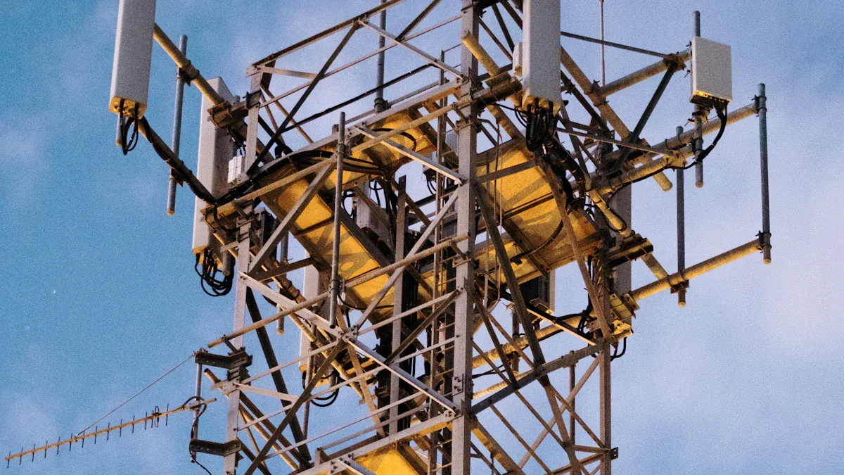
In industrial environments, SPDs prove essential for protecting critical infrastructure from transient overvoltages. Telecom towers, for example, use specialized surge protectors to guard base stations against lightning-induced surges. This protection ensures continuous network operation, even in harsh weather conditions.
Investing in comprehensive surge protection helps maintain uninterrupted service and supports the overall resilience of telecom networks.
Output Distribution
Load Management
Telecom rectifier systems must distribute power efficiently to multiple devices. Each device, or load, requires a specific amount of current and voltage. The system uses load management strategies to balance these demands. Operators group loads based on priority and function. Critical equipment, such as core network switches, receives power first. Less essential devices connect to secondary outputs.
Modern rectifier systems use modular designs. Each module operates independently. This structure allows technicians to add or remove modules as network needs change. Plug-and-play features make upgrades simple. About 37% of new rectifiers support this easy expansion. Digital controls monitor each output in real time. These controls adjust power delivery to match changing demands. This approach prevents overloads and ensures stable operation.
Effective load management reduces downtime and extends equipment life. It also supports network growth by allowing for future expansion.
Power Delivery
Power delivery in telecom rectifier systems focuses on reliability and efficiency. The system must provide consistent DC power to all connected loads. High energy efficiency remains a key goal. Many designs achieve over 90% efficiency, with some reaching up to 94.6%. This reduces energy costs and environmental impact.
The table below highlights important features that optimize power delivery:
Feature | Description |
|---|---|
Modular Design | Independent modules enhance reliability and reduce downtime. |
n+1 Redundancy | Extra modules provide backup, ensuring high availability for critical applications. |
Scalability | Additional modules support network expansion, meeting future demands. |
Energy Efficiency | High-efficiency systems reduce costs and environmental impact, achieving up to 94.6% efficiency. |
Load Capacity | Systems adapt to varying loads, ensuring uninterrupted service for high-demand applications. |
Scalable rectifier systems allow operators to adjust capacity without major changes. Digital controls enable real-time adjustments, maintaining performance even as loads shift. These features ensure that telecom networks deliver reliable service, even during peak demand.
Cooling and Thermal Management
Cooling Methods
Telecom rectifier systems generate heat during operation. Managing this heat is essential for maintaining system performance. Engineers use several cooling methods to keep temperatures within safe limits.
Forced Air Cooling: Most telecom rectifier systems use forced air cooling. Fans move air across internal components, carrying heat away from sensitive parts. This method works well in high-density installations where equipment produces significant heat.
Convection Cooling: Some models, such as the IPack65, rely on convection cooling. This approach does not use fans. Instead, it depends on the natural movement of air. As warm air rises from hot surfaces, cooler air replaces it, creating a continuous flow that removes heat. Convection cooling reduces maintenance needs because there are no moving parts to replace.
Both methods help prevent overheating. Forced air cooling offers strong performance in demanding environments. Convection cooling provides a quieter and lower-maintenance solution for specific applications.
Proper cooling ensures that telecom rectifier systems operate efficiently, even in harsh outdoor conditions.
Reliability Impact
Effective thermal management directly affects the reliability and lifespan of telecom rectifier systems. High temperatures can damage electronic components and cause early failures. By using techniques such as heat sinks, forced-air cooling, or convection cooling, engineers control thermal resistance and improve heat transfer.
When systems maintain stable temperatures, the risk of hot spots decreases. Hot spots can lead to component failure and reduce equipment lifespan. Efficient cooling strategies, such as fan cooling, help distribute heat evenly and prevent these issues. In challenging environments, proper thermal management becomes even more important.
Operators who invest in robust cooling solutions see fewer thermal-related failures. Their equipment lasts longer and performs more reliably. Consistent thermal control supports stable operation and reduces the need for emergency repairs.
Good thermal management extends the operational life of telecom rectifier systems and supports dependable network performance.
Advanced Features
Battery Backup
Battery backup stands as a critical feature in any Telecom Rectifier System. Batteries store energy and supply power when the main grid fails. This backup ensures that telecom networks continue to operate during outages. Advanced systems use intelligent battery management to monitor charge levels, temperature, and health. These features help extend battery life and improve reliability. Operators can trust that their networks will remain active, even in challenging conditions.
Communication Interfaces
Modern telecom rectifier systems support a wide range of communication interfaces. These interfaces allow operators to monitor and control power systems remotely. The table below shows common protocols and ports found in advanced systems:
Communication Protocols | Description/Notes |
|---|---|
HTTP | Commonly supported for remote monitoring |
SNMP (v2, v3) | Secure and reliable; SNMPv3 Proxy supported |
YDN23 | Supported protocol |
RS 232 | Built-in port for remote control |
RS 485 | Supported serial interface |
Ethernet | Enables network connectivity |
USB | Supported interface |
IPv4, IPv6 | Supported internet protocols |
HTTPS | Secure HTTP protocol supported |
Modbus | Common in generator and rectifier monitoring |
Dry Contacts | Used for alarm inputs/outputs and integration |
These interfaces make it easy to integrate the rectifier system with network management tools. Operators can receive alerts, check system status, and perform diagnostics from any location.
Redundancy Options
Redundancy improves system availability and reliability. In telecom rectifier systems, redundancy means adding extra modules or duplicating the entire system. The table below compares common redundancy models:
Redundancy Model | Description | Advantages | Disadvantages |
|---|---|---|---|
N+1 | Adds one extra unit to the required number | Cost-effective, allows for single failure | Vulnerable to multiple failures |
2N | Duplicates the entire system | Ensures uninterrupted service, handles full load | Higher investment, requires more space |
Redundant designs help detect problems early with IoT sensors and AI. They also enable faster maintenance and reduce downtime. Operators benefit from higher service availability and improved network stability.
ESTEL Integration
ESTEL offers advanced integration features in its Telecom Rectifier System. The table below highlights key features:
Feature | Description |
|---|---|
Hot swappable Rectifier Modules | Allows for easy replacement without system downtime |
N + 1 redundancy | Ensures reliability by allowing one module to fail without affecting system performance |
Wide input voltage range | Operates between 90-280 Vac, providing flexibility in various environments |
High efficiency | Achieves efficiency levels of ≥92%, reducing energy costs |
Active power factor compensation | Maintains a power factor greater than 0.98, improving energy usage |
Operating temperature range | Functions effectively in temperatures from -25℃ to +55℃ |
Auto current sharing | Facilitates parallel operation of multiple modules for balanced load distribution |
Surge protection | Offers protection against surges up to 20KA |
Advanced battery management | Enhances battery life and performance |
DC power distribution options | Provides flexibility in power distribution setups |
ESTEL designs its systems for environmental adaptability. These features ensure reliable operation in harsh outdoor conditions and support the evolving needs of telecom operators.
Each core component in a telecom rectifier system plays a vital role in delivering stable, efficient power. The power input module, transformer, rectifier, filters, regulators, control units, safety features, and cooling systems all work together to ensure network reliability. The table below highlights key performance indicators:
Performance Aspect | Statistic | Explanation |
|---|---|---|
Efficiency | Reduces energy loss and costs | |
Reliability | N+1 redundancy | Ensures continuous power |
Downtime Reduction | 25% | Improves network reliability |
Innovations such as higher efficiency, renewable energy integration, and advanced materials drive future success. Quality and innovation in rectifier systems ensure safety, promote longevity, and enhance operational efficiency. Choosing trusted providers like ESTEL supports business success and reliable telecom infrastructure.
FAQ
What is the main purpose of a telecom rectifier system?
A telecom rectifier system converts AC power from the grid into stable DC power. Telecom equipment needs DC power to operate reliably. This system ensures continuous service for communication networks.
How does ESTEL’s modular design benefit telecom operators?
Operators can add or replace modules without shutting down the system. This modular approach allows for easy expansion and maintenance. It helps reduce downtime and supports network growth.
Why is voltage regulation important in telecom rectifier systems?
Voltage regulation keeps the DC output steady. Stable voltage protects sensitive telecom devices from damage. It also ensures that backup batteries charge correctly.
What safety features do ESTEL rectifier systems include?
ESTEL rectifier systems use fuses, circuit breakers, and surge protection. These features guard against overloads, short circuits, and voltage spikes. They help maintain safe and reliable operation.
See Also
Introductory Guide to Telecom Power Supply Systems
Methods for Calculating Telecom Cabinet Power and Batteries
Telecom Cabinets with Grid-Linked Solar Inverter Systems
CALL US DIRECTLY
86-13752765943
3A-8, SHUIWAN 1979 SQUARE (PHASE II), NO.111, TAIZI ROAD,SHUIWAN COMMUNITY, ZHAOSHANG STREET, NANSHAN DISTRICT, SHENZHEN, GUANGDONG, CHINA