EMC Shielding for Telecom Power Systems: Metal Shielding Layers vs Conductive Coatings

You will find that metal shielding layers usually deliver the most robust EMC protection for telecom power systems. As 5G networks expand, the need for high-performance EMC shielding grows. Complex electronic devices require effective shielding to prevent interference in high-frequency environments. In these settings, you often see two main approaches: solid metal layers and conductive coatings. Each method offers unique strengths and limitations.
Key Takeaways
Metal shielding layers provide strong protection against electromagnetic interference (EMI) in telecom power systems. Use copper or aluminum for high-frequency environments.
Conductive coatings offer flexibility and can cover complex shapes, but they may not block EMI as effectively as solid metal layers. Consider them for less demanding applications.
Always check the durability and environmental resistance of your shielding materials. Corrosion-resistant options last longer and save money on repairs.
Follow industry standards for EMI shielding to ensure your telecom systems operate reliably. Meeting these standards protects your equipment and communication.
Plan your shielding choice early in the design process. This helps you avoid costly changes and ensures the best results for your project.
Effectiveness Comparison
Metal Shielding Layers
You will notice that metal shielding layers set the standard for electromagnetic compatibility in telecom power systems. These layers use solid metals like copper, aluminum, or steel to block electromagnetic interference (EMI). Their effectiveness comes from high electrical conductivity and the ability to absorb and dissipate unwanted signals.
Tip: You can select different metals based on the frequency range and environment of your telecom power systems.
Here is a table that shows how common metals perform across various frequency ranges:
Material | Frequency Range | Key Property | Application Example |
|---|---|---|---|
Copper | High-Frequency | High Conductivity | Cellular base stations, Wi-Fi routers |
Aluminum | High-Frequency | Lightweight, Corrosion Resistant | Aerospace, automotive structures |
Steel | Low-Frequency | High Magnetic Permeability | Industrial equipment, transformers |
Mu-Metal | Extreme Low-Frequency | Exceptional Permeability | Medical imaging rooms |
Coated Copper | Humid/Corrosive | High Conductivity with Durability | Telecom cabinets in harsh environments |
You will find that copper and aluminum work best for high-frequency shielding, which is common in telecom power systems. Steel and mu-metal serve better in low-frequency or specialized applications.
Laboratory and field tests show that metal shielding layers mainly absorb electromagnetic energy. This absorption mechanism provides strong EMI suppression, especially in environments with high-frequency signals. You can rely on these layers for consistent performance in demanding telecom settings.
Conductive Coatings
Conductive coatings offer a different approach to EMI shielding. You apply these coatings as thin layers of conductive paint or metal onto plastic or composite surfaces. They reflect electromagnetic waves rather than absorb them.
Conductive coatings use reflection as the main shielding mechanism.
The electrical conductivity of pure copper is higher than that of copper-zinc or copper-nickel coatings.
Thicker coatings improve conductivity because they contain more connected metal particles.
High porosity in coatings, such as in copper-nickel, lowers conductivity and reduces shielding effectiveness.
You will see that conductive coatings provide flexibility and can cover complex shapes. However, their lower conductivity compared to solid metals means they may not block EMI as effectively in telecom power systems. In high-EMI environments, you might notice performance gaps, especially at higher frequencies.
Note: Conductive coatings can work well for moderate EMI control, but you should consider the specific needs of your telecom power systems before choosing this method.
Telecom Power Systems Applications
Shielding Requirements
You face strict requirements when you design EMC shielding for telecom power systems. These systems operate in environments filled with high-frequency signals and sensitive electronics. Even a small amount of electromagnetic interference can disrupt communication, cause data loss, or damage equipment. To prevent these issues, you must follow industry and regulatory standards that set clear limits for emissions and immunity.
Here is a table that summarizes some of the most important standards you should know:
Standard | Description |
|---|---|
CISPR 11 | Limits radio disturbance for industrial, scientific, and medical equipment. |
CISPR 22/32 | Sets emission limits for IT and communication devices, including power supplies. |
IEC 61000-4-2~6 | Covers immunity testing to ensure devices withstand external interference. |
IEC 61000-3-2 | Limits harmonic current emissions for power supplies and converters. |
EN 55032 | Restricts emissions for multimedia equipment in Europe. |
FCC Part 15 | Sets emission levels for devices in the United States. |
You must also consider shielding effectiveness. For example, MIL-STD-285 requires a minimum of 100 dB shielding from 20 to 10,000 hertz in high-EMI environments. Meeting these standards helps you protect both your equipment and your network reliability.
Environmental Factors
You will encounter many environmental challenges in telecom power systems. Temperature swings, humidity, and exposure to chemicals can all affect the performance of your shielding. If you use conformal or moisture-resistant coatings, you can protect electronics from dust, moisture, and corrosion. Hydrophobic coatings help repel water, which prevents short circuits and extends the life of your devices.
When you select materials, you should look for corrosion resistance. Stainless steel and thicker shielding materials last longer in harsh environments. A smooth surface finish also helps reduce corrosion and keeps your shielding effective over time.
Tip: Always check the durability and surface finish of your shielding materials. This step ensures long-term protection for your telecom power systems, even in tough conditions.
Metal Shielding Layers

Materials and Properties
You use metal shielding layers to block unwanted electromagnetic interference in electronic equipment. These layers consist of solid sheets or enclosures made from metals with high electrical conductivity. The most common metals for shielding include:
Brass: Often used for EMI shielding in various devices.
Copper: Delivers high conductivity, making it excellent for reflecting electromagnetic waves.
Aluminum: Weighs less than copper and costs less, but offers about 60% of copper’s conductivity. It can corrode if not protected.
Silver: Provides the highest conductivity and good resistance to corrosion, but comes at a higher price.
Nickel: Used in many shielding applications for its unique properties.
Steel: Adds strength and offers both magnetic and electrical shielding.
Tin: Commonly used as a coating on other metals to improve performance.
You select the metal based on your needs. For example, copper works best when you need top electrical and thermal performance. Aluminum suits you if you want to save weight and reduce costs, especially in large enclosures. Silver gives you the best conductivity but may not fit your budget for most telecom power systems.
Tip: Always consider both the conductivity and the environment when choosing a metal for shielding.
Pros and Cons
You gain several important benefits when you use metal shielding layers in telecom power systems:
They confine electric fields, which keeps your equipment safe and protects people from electrical hazards.
They create a grounded barrier that blocks external electromagnetic interference. This helps you maintain signal quality and meet strict EMC standards.
They provide reliable, long-lasting protection in harsh environments, especially when you choose corrosion-resistant metals.
However, you also face some limitations:
Metal shields can struggle with high-frequency signals. Resonance effects may reduce their effectiveness.
Thin metal layers might not block magnetic fields well, allowing some interference to pass through.
Bulkiness and shaping difficulties can make it hard to use metal shielding in small or complex devices.
Metals can corrode over time, especially in humid or harsh environments, which reduces their shielding ability.
The need for precise shaping can complicate your design and manufacturing process.
You should weigh these pros and cons carefully. Metal shielding layers offer strong protection, but you must consider the physical and environmental challenges in your application.
Conductive Coatings
Types and Application
You can use conductive coatings as an alternative to solid metal shielding in many electronic devices. These coatings include paints and metal layers applied to plastics or polymers. You often see them in the form of silver, copper, or specialized epoxy-based coatings. Each type offers unique benefits for different needs.
Here is a table that shows some common types of conductive coatings and their typical uses:
Coating Type | Description | Typical Applications |
|---|---|---|
Silver | Excellent electric and thermal conductivity | Widely used in telecom applications and mirrors |
Copper | Highly conductive, resists corrosion | Semiconductors, printed circuit boards |
Aluminum-Filled Epoxies | Moderate electrical and good thermal conductivity | Used when weight reduction is important |
Graphite-Filled Epoxies | Excellent conductor, handles mechanical stress | Sliding or rotating electrical contacts |
Carbon-Filled Epoxies | Balanced conductivity and cost-effectiveness | Reliable electrical paths in various devices |
You can apply these coatings using several methods. Spraying gives you high shielding effectiveness but may reduce adhesion and flexibility. Dipping helps you achieve a uniform thickness, though it works best on simple shapes. Brushing allows for precise application, but you might see uneven coverage. The method you choose affects the coating’s thickness and uniformity, which directly impacts how well it blocks electromagnetic interference. Some highly conductive epoxy coatings can reach over 85 dB of shielding at just 25 microns thick, showing that careful application can deliver strong results in Telecom Power Systems.
Pros and Cons
You gain several advantages when you use conductive coatings for EMC shielding. These coatings offer flexibility and can cover complex shapes that metal shields cannot. You can also control the thickness for consistent performance. Many coatings resist abrasion and harsh environments, making them durable in tough conditions.
Here is a table that highlights the main advantages:
Advantage | Description |
|---|---|
Exceptional point-to-point resistivity | Enhances shielding effectiveness |
Material flexibility | Choose from nickel, copper, or graphite for cost savings |
Significant abrasion resistance | RFI coatings last longer at contact points |
Uniform thickness application | Ensures consistent performance |
Reliable electromagnetic conductivity | Maintains steady shielding over time |
Withstands humidity and salt spray for longer life |
However, you should know the limitations. Conductive coatings may not match the shielding power of solid metal layers, especially in high-EMI environments. Thinner coatings or uneven application can create weak spots. Over time, some coatings may wear down or lose conductivity if exposed to harsh chemicals or physical abrasion. You need to balance cost, performance, and durability when choosing this method for your Telecom Power Systems.
Tip: Always test the coating’s effectiveness in your specific environment before full-scale use.
Cost and Maintenance
Initial Investment
When you plan your EMC shielding, you need to consider both the upfront cost and the installation process. Metal shielding layers usually require a higher initial investment. You pay more for materials like copper or stainless steel, and you may need skilled labor for fabrication and assembly. Conductive coatings, on the other hand, often cost less at the start. You can apply these coatings quickly to plastic or composite parts, which saves time and reduces labor expenses.
Here is a table that highlights the strengths and best uses of common shielding materials:
Material | Strengths | Best Use |
|---|---|---|
Stainless Steel | Rust-resistant, very strong | Wet or coastal areas |
Aluminum | Lightweight, resists rust | General outdoor use |
Fiberglass-Reinforced Plastic | Handles extreme heat or cold | Hot or freezing places |
Using corrosion-resistant materials saves you money over time because you avoid frequent repairs.
Durability and Upkeep
You want your shielding to last for years with minimal maintenance. Metal shielding layers, especially those made from corrosion-resistant metals, offer strong durability. Regular maintenance checks help you catch problems early and prevent costly repairs. Surge protection devices also reduce repair costs and improve network reliability.
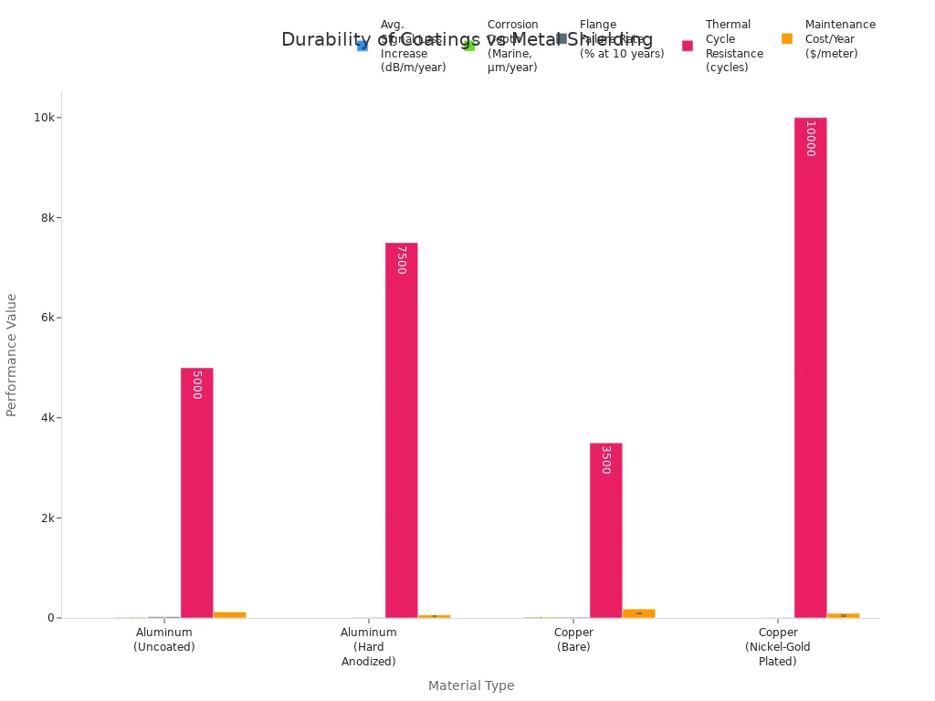
Over a 10-year period, metal shielding layers show better performance than conductive coatings. The table below compares key durability metrics:
Performance Metric | Aluminum (Uncoated) | Aluminum (Hard Anodized) | Copper (Bare) | Copper (Nickel-Gold Plated) |
|---|---|---|---|---|
Avg. Signal Loss Increase | 0.08 dB/m/year | 0.03 dB/m/year | 0.05 dB/m/year | 0.01 dB/m/year |
Corrosion Depth (Marine) | 12 µm/year | 2 µm/year | 18 µm/year | <1 µm/year |
Flange Failure Rate | 22% at 10 years | 8% at 10 years | 15% at 10 years | 3% at 10 years |
Thermal Cycle Resistance | 5,000 cycles | 7,500 cycles | 3,500 cycles | 10,000 cycles |
Maintenance Cost/Year | $120/meter | $60/meter | $180/meter | $90/meter |
You can further improve durability by following these steps:
Fabricate enclosures from as few pieces as possible to reduce failure points.
Use RF gaskets for removable parts to maintain shielding.
Design panels for controlled gasket compression to prevent leaks.
If you choose the right materials and follow good maintenance practices, you will get the best long-term value for your Telecom Power Systems.
Choosing the Right Solution
Decision Factors
When you select an EMC shielding method, you need to weigh several important factors. Each project brings its own set of challenges, so you should look at the following points before making a decision:
Electrical Requirements: You must decide if your application needs to allow electrical current to pass or if you need to block it. Conductive coatings let current flow, while non-conductive coatings stop it.
Environmental Resistance: Think about how your shielding will handle moisture, chemicals, and temperature changes. Non-conductive coatings often resist corrosion better, but conductive coatings may face issues over time.
Application Methods: Conductive coatings need careful and precise application. This can raise costs and take more time compared to non-conductive options.
Cost Considerations: You should compare the total cost, including materials and labor. Conductive coatings can cost more because of their application process, while non-conductive coatings may save you money.
Space and Weight Constraints: Many telecom projects have strict limits on size and weight. You need to choose a shielding method that fits your design without adding too much bulk.
EMI Levels and Project Demands: High levels of electromagnetic interference require stronger shielding. You should match your solution to the EMI environment and the sensitivity of your equipment.
Design and Installation Timing: You get better results when you plan for shielding early in the design process. This helps you meet all project requirements and avoid costly changes later.
Tip: Always consider the unique needs of your project. Early planning and careful selection help you avoid problems down the road.
You have seen that metal shielding layers usually give you the strongest EMC protection for telecom power systems. These layers offer high durability and reliable performance, but they can cost more and add weight. Conductive coatings provide flexibility and lower costs, yet they may not block strong EMI as well.
Choose metal shielding layers for high-EMI environments or critical systems.
Use conductive coatings for lighter, less demanding applications.
Always match your shielding choice to your system’s needs for the best results.
FAQ
What is the main difference between metal shielding layers and conductive coatings?
You use metal shielding layers as solid barriers made from metals like copper or aluminum. You apply conductive coatings as thin layers of conductive paint or metal onto surfaces. Metal layers usually block EMI better than coatings.
Can you combine metal shielding layers and conductive coatings?
Yes, you can combine both methods. You might use a metal enclosure for strong EMI protection and add a conductive coating to cover seams or complex shapes. This approach gives you extra shielding in critical areas.
How do you test the effectiveness of EMC shielding?
You measure shielding effectiveness using specialized equipment. You check how much electromagnetic interference passes through the shield. Most labs follow industry standards like MIL-STD-285 or IEC 61000 to ensure accurate results.
Do conductive coatings wear out faster than metal layers?
Conductive coatings can wear down over time, especially in harsh environments. You may see reduced performance if the coating gets scratched or exposed to chemicals. Metal layers usually last longer and resist damage better.
Which method works best for outdoor telecom equipment?
You should choose metal shielding layers with corrosion-resistant finishes for outdoor use. These layers handle weather, moisture, and temperature changes better than most conductive coatings. Always check the environment before making your choice.
See Also
The Superiority Of Lithium Batteries In Telecom Equipment
Essential Tips For Safeguarding Outdoor Telecom Equipment
Exploring Various Cooling Techniques For Telecom Cabinet Efficiency
Understanding Wires Versus Cables In Telecom Cabinet Use
Ensuring Consistent Power Supply For Telecom Cabinet Operations
CALL US DIRECTLY
86-13752765943
3A-8, SHUIWAN 1979 SQUARE (PHASE II), NO.111, TAIZI ROAD,SHUIWAN COMMUNITY, ZHAOSHANG STREET, NANSHAN DISTRICT, SHENZHEN, GUANGDONG, CHINA