Implement N+1 redundancy in -48V DC power systems

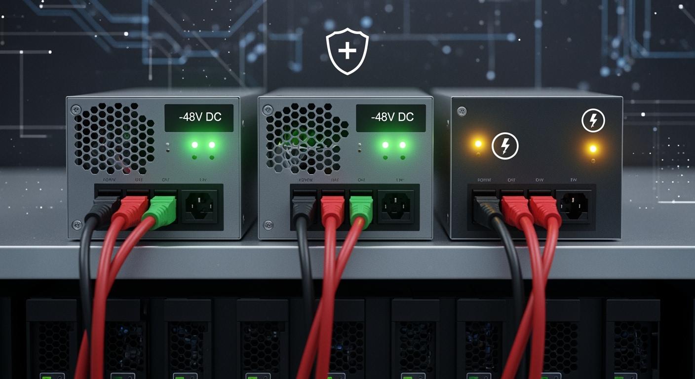
You depend on your telecom network to stay connected every moment. N+1 redundancy means you add one extra power module to your system. This extra module steps in if another fails, keeping your -48V DC telecom equipment running. When you compare a basic setup with a redundant one, the difference is clear:
Configuration | Description | Impact on Uptime |
|---|---|---|
N (Non-redundant) | Single component | Higher risk of downtime due to failure |
N+1 | One additional component | Allows for continued operation during failure or maintenance, statistically improving uptime |
You need high reliability for telecom infrastructure. ESTEL provides trusted solutions such as the Telecom Power System and Telecom Rectifier System. These help you achieve the redundancy your network requires.
Key Takeaways
N+1 redundancy adds one extra power module to your system, ensuring continuous operation during failures.
This setup significantly improves uptime, allowing maintenance without service interruptions.
Investing in N+1 redundancy may increase initial costs but leads to long-term savings through reduced outages and lower maintenance needs.
Regular testing and maintenance of your N+1 system are crucial for reliability and performance.
Choose modular systems for easy upgrades and scalability as your telecom network grows.
N+1 Redundancy in Telecom Power Systems
What is N+1 Redundancy?
You often hear about N+1 redundancy when you look for ways to improve reliability in telecom networks. N+1 redundancy means you install one extra power module beyond what your system needs to operate. For example, if your equipment requires two power modules (N=2), you add a third module. This extra module steps in if one fails, so your system keeps running without interruption. Industry standards define N+1 redundancy as a setup that includes one additional component beyond the minimum required capacity. This approach ensures that if one component fails, the extra module takes over, maintaining system reliability.
Application in -48V DC Systems
You see N+1 redundancy most often in -48V DC telecom power systems. These systems power critical telecom equipment, so uptime is essential. In a typical setup, you use several power supply units to meet your load requirements. With N+1 redundancy, you add one more unit than you need. If one unit fails, the others share the load, and your equipment continues to operate. This configuration allows you to perform maintenance or replace a faulty module without shutting down your network. You benefit from higher availability and less risk of service interruption.
Tip: N+1 redundancy lets you maintain and upgrade your power system without affecting your telecom services.
ESTEL’s Role in Redundant Solutions
You can rely on ESTEL for robust N+1 redundancy solutions. ESTEL designs its Telecom Power System and rectifier systems to support modular configurations. You can easily add or replace modules to achieve N+1 redundancy. The systems offer flexible installation options, such as rack-mount or cabinet integration, making them suitable for different telecom environments. ESTEL’s focus on quality and innovation ensures that your network remains reliable, even in harsh outdoor conditions. By choosing ESTEL, you invest in a solution that keeps your telecom infrastructure running smoothly and efficiently.
Benefits of N+1 Redundancy
Reliability and Uptime
You want your telecom network to work all the time. N+1 redundancy helps you reach this goal. When you use an extra power module, your system keeps running even if one module fails. This means your network stays online during repairs or unexpected problems. You do not need to shut down your equipment for maintenance. The Telecom Power System supports this setup, so you can trust your network to deliver reliable service. Over time, you see fewer outages and less downtime.
Here is a quick look at how N+1 redundancy affects your costs:
Aspect | Description |
|---|---|
Initial Investment | N+1 configurations require purchasing additional modules, increasing upfront capital expenditure. |
Long-term Savings | Investing in reliable rectifiers can lead to significant savings over time due to lower failure rates. |
Maintenance Costs | Modular systems allow for easy replacement of faulty modules, minimizing downtime and labor costs. |
You may spend more at first, but you save money in the long run because your system lasts longer and needs less emergency repair.
Risk Mitigation
You face many risks in telecom operations. Power module failure is one of the biggest threats to uptime. N+1 redundancy lowers this risk. If one module stops working, the extra module takes over. You avoid sudden outages and keep your network stable. You can also plan maintenance without rushing, since your system keeps running. This approach gives you peace of mind and protects your business from costly interruptions.
Scalability for Telecom Networks
Your network may grow as you add more users or services. N+1 redundancy makes it easy to scale your power system. You can add more modules as your needs increase. The modular design of the Telecom Power System lets you expand without major changes.
N+1 Redundancy is similar to N Redundancy, but with additional components that will counteract equipment failure.
For larger businesses that can afford the extended maintenance of a more complex backup system, the N+1 Redundancy is a shoo-in. Its ability to provide both a mirror image and additional working components provides everyone peace of mind.
You can build a flexible and future-proof network by choosing a scalable power solution.
Implementation Steps for Telecom Power System

Assessing Power Load
You must start by understanding how much power your telecom site needs. Accurate load assessment ensures your system can handle both current and future demands. Begin by listing all equipment that will connect to the -48V DC system. Check the power ratings for each device. Add up the total current draw. Always consider future growth. Many experts recommend planning for at least three years ahead.
You should also pay attention to the voltage range your equipment requires. The table below shows common voltage ranges for -48V DC telecom systems:
Voltage Range | Minimum Voltage | Maximum Voltage | Notes |
|---|---|---|---|
Range 1 | 42.75 V | 56.7 V | Accommodates equipment with highest minimum voltage needs. |
Range 2 | 40.0 V | 56.7 V | Aligns with end-of-discharge scenarios for battery voltage. |
Tip: Always use the highest minimum voltage requirement when sizing your system. This ensures every device operates safely.
Selecting Rectifiers and Modules
After you know your power load, you can choose the right rectifiers and modules. Rectifiers convert AC power to the DC voltage your telecom equipment needs. For N+1 redundancy, select one more rectifier module than your calculated load requires. If your site needs three modules, install four. This extra module keeps your system running if one fails.
Look for rectifier systems with high efficiency. Even a small improvement in efficiency can save energy and reduce costs over time. ESTEL’s Telecom Rectifier System offers modular designs and high efficiency rates above 96%. You can easily add or replace modules as your network grows.
System Design and Layout
Designing your system layout is a critical step. You need to plan for capacity, efficiency, and site constraints. Follow these steps for best results:
Calculate your total load and add one extra module for N+1 redundancy.
Plan for future growth by considering projected increases in power demand.
Choose equipment rated for high ambient temperatures to reduce cooling needs.
Verify rack size (19” or 23”), DC busbar layout, cable routing, and grounding.
Ensure proper lightning protection for outdoor sites.
You can install the Telecom Power System on a standard 19-inch rack or inside a cabinet. This flexibility helps you adapt to different site requirements.
Installation and Integration
When you install your system, follow industry best practices to ensure reliability:
Use hot-swappable rectifier modules. You can replace these without shutting down your network.
Configure dual AC/DC power inputs if possible. This setup provides continuous power, even during maintenance.
Integrate intelligent monitoring platforms. These systems detect failures early and switch to backup modules automatically.
Balance preventive maintenance with real-time monitoring. This approach reduces downtime and optimizes costs.
Note: Effective maintenance and smart monitoring help you deliver consistent, high-quality telecom services.
Testing Redundancy
Testing your N+1 redundancy setup is essential. You want to make sure your backup systems work when needed. Follow these steps:
Schedule regular tests and maintenance for all backup modules.
Run automated failover simulations. These tests show if the extra module takes over when a failure occurs.
Review key performance indicators like latency, throughput, and packet drops. These metrics help you measure the success of your redundancy plan.
Regular testing gives you confidence that your Telecom Power System will perform during real emergencies.
By following these steps, you can implement a reliable, scalable, and efficient N+1 redundant power system for your telecom network.
Best Practices and Common Pitfalls
Maintenance and Monitoring
You must keep your N+1 redundant power system in top condition. Regular maintenance prevents unexpected failures and extends equipment life. Use a structured schedule for inspections and tests. The table below shows a typical maintenance plan for telecom power systems:
Maintenance Interval | Tasks to Perform |
|---|---|
Monthly | Visual inspection, check ventilation, test batteries, review monitoring results |
Quarterly | Inspect for damage, measure cell voltage, check battery temperatures |
Semi-Annual | Inspect connections, clean equipment, test system operation |
Annual | Power down and inspect all parts, conduct load test, measure torque, run tests |
Routine inspections help you spot problems early. Technicians look for swelling, corrosion, or damage. Real-time monitoring tools, like those in ESTEL’s Telecom Power System, alert you to issues before they cause downtime. Predictive maintenance technology also plays a key role. It identifies potential problems early and helps you avoid unexpected shutdowns.
Documentation and Planning
You need clear and complete documentation for your N+1 system. Good records make troubleshooting easier and speed up repairs. Include system architecture, failover steps, and maintenance schedules in your documents. Train your staff so they know how to handle redundancy protocols and emergencies. Well-trained teams with access to thorough documentation can resolve issues quickly and keep your network running.
Comprehensive documentation and staff training are critical for success.
Detailed records should cover architecture, procedures, and schedules.
Training ensures your team responds well during emergencies.
Avoiding Mistakes in N+1 Implementation
You can avoid common mistakes by following best practices. Do not skip regular maintenance or ignore monitoring alerts. Always size your system for future growth. Use modular systems, like ESTEL’s Telecom Rectifier System, to make upgrades and repairs simple. Never overlook staff training or documentation. These steps help you maintain uptime and protect your investment.
Tip: Plan for expansion from the start. Modular and scalable systems make it easy to add capacity as your network grows.
You can secure your telecom network by following clear steps for N+1 redundancy. Start with accurate load assessment, select modular rectifiers, design for growth, and test your system often. The Telecom Power System from ESTEL delivers reliable power and advanced features that keep your network running.
Feature | Benefit |
|---|---|
High Energy Efficiency | Reduces energy use and power loss, saving costs |
N+1 Redundancy | Maintains uptime and prevents service interruptions |
Quick ROI | Offsets rising energy costs and boosts financial results |
Stay committed to best practices for long-term performance and peace of mind.
FAQ
What does N+1 redundancy mean for my telecom power system?
N+1 redundancy means you install one extra power module beyond your system’s minimum requirement. If one module fails, the extra module keeps your telecom equipment running without interruption.
How do I choose the right rectifier modules for N+1 redundancy?
You should first calculate your total power load. Select rectifier modules that meet this load, then add one extra module for redundancy. ESTEL’s modular rectifier systems make this process simple and scalable.
Can I upgrade my existing system to N+1 redundancy?
Yes, you can upgrade most modular systems. You add an extra rectifier module to your current setup. ESTEL’s Telecom Power System supports easy upgrades for improved reliability.
How often should I test my N+1 redundant system?
You should test your system at least twice a year. Regular testing ensures your backup modules work properly and your network stays reliable.
Tip: Schedule tests during low-traffic periods to avoid service disruption.
See Also
Ensuring Consistent Power Supply for Telecom Equipment Cabinets
Solar Inverter and Battery Solutions for Telecom Cabinet Power
Calculating Power Systems and Battery Needs for Telecom Cabinets
How ESTEL Maintains Optimal Voltage Levels in Telecom Cabinets
CALL US DIRECTLY
86-13752765943
3A-8, SHUIWAN 1979 SQUARE (PHASE II), NO.111, TAIZI ROAD,SHUIWAN COMMUNITY, ZHAOSHANG STREET, NANSHAN DISTRICT, SHENZHEN, GUANGDONG, CHINA