How Modular Expansion Design Keeps Telecom Rectifier Systems Running


Can you add DC power at a working telecom site without turning it off? Older systems needed planned outages, risky switchovers, or replacing the whole plant. Telecom Rectifier Systems with hot-swap modules, N+1 redundancy, and controller-based management make shutdown-free expansion the normal way. This setup lets you add power without stopping service. You will learn how it works, where it helps, and how to plan a system that can grow.
Key Takeaways
Hot-swap modules let you add power without turning off your network.
With N+1 redundancy, your site keeps working even when one module fails.
Remote monitoring helps you plan for more capacity before you run out.
Modular design saves money because it stops you from buying too much power and needing to send repair trucks.
This method helps 5G grow in more places and supports faraway sites with fewer trips.
Why Legacy Telecom Rectifier Systems Force Shutdowns
Old rectifier plants cannot grow without stopping service. The modules inside them are not hot-swappable. Once they are installed, the capacity stays the same. To add power, you must plan an outage, do a risky cutover, or replace the whole system. Each choice disrupts your network and causes delays for your team.
The real cost of planned outages
A planned outage sounds easy on paper, but the costs add up fast. You need a truck roll. A technician must drive to the site, often at night to reduce customer impact. That one visit can cost hundreds of dollars.
A single truck roll may cost between a few hundred and over a thousand dollars, depending on labor and location.
Overtime labor makes the price even higher. Night or weekend work means premium pay rates. If your own team cannot do the job, you hire outside help at an even higher cost.
Then come the SLA penalties. Service level agreements promise uptime for your customers. A planned outage still counts against your metrics. You risk losing money from customers who expect always-on service. The cutover itself carries risk. If something goes wrong, the planned outage turns into an unplanned one that lasts much longer. Recovery takes more time, more truck rolls, and more money.
Every outage, even a scheduled one, creates a window of weakness. You cannot afford that risk in a competitive telecom market. Operators with traditional Telecom Rectifier Systems often fear capacity upgrades for this exact reason.
Over-provisioning as the old workaround
Another way to avoid outages is to over-provision when you build. You install much more capacity than you need today. You hope to never touch the system again as load grows.
This approach wastes capital. You spend money on rectifier modules you do not use for months or years. That cash could go toward network expansion. The extra equipment also takes up valuable rack space. A larger cabinet adds cost and uses floor area you could use for other gear.
Efficiency suffers too. Rectifiers run best near their rated load. At low load, efficiency drops a lot. You pay for electricity that does no useful work. The energy loss adds up over the system lifetime, raising your operating expenses.
Over-provisioning seems like a simple fix. In practice, it ties up resources, wastes space, and lowers efficiency. The real solution is a modular design that lets you add capacity without shutdowns.
How Modular Design Enables Live Expansion in Telecom Rectifier Systems
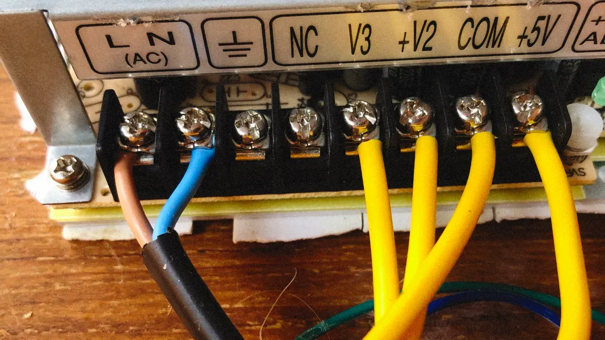
A rectifier module takes AC power from the utility grid or a generator and turns it into steady -48V DC. This DC output powers your telecom equipment and charges your batteries. In a modular system, you set up several rectifier modules side by side. They work together under a system controller. The controller balances the load across all modules. This building-block approach changes everything about how you add capacity.
Hot-swap modules and parallel operation
Hot-swap means you can add or swap a module without shutting down the plant. You slide the new module into an empty slot. The controller finds it and starts sharing the load. No outage. No risky cutover. No truck roll at midnight.
The controller manages load sharing in a smart way. It spreads current evenly across all active modules. If one module carries more load than others, the controller adjusts. This keeps every module within its safe operating range. You get steady -48V DC output even as you add or remove modules.
You can also swap a failed module the same way. Pull it out. Push in a spare. The system keeps running. Your network stays live. This is the main advantage of modular design over legacy fixed-capacity plants.
N+1 redundancy and remote monitoring
N+1 redundancy means you size your capacity so one module can fail or be pulled for service while the rest carry the full load. If your site needs 100A and each module gives 50A, you install three modules. Two carry the load. One stands by as backup. When a module fails, the other two keep your site running without a break.
Remote monitoring makes this even more powerful. The system controller reports module status, load levels, and alarms to your network operations center. You see exactly how much headroom you have. You plan expansion before capacity runs out, not after.
Common protocols for this reporting include SNMP, Modbus, and dry contacts. SNMP uses an object model with OIDs and supports polling plus event notifications like traps. It suits IP-aware rectifiers and site gateways that need detailed module-level health data. Modbus uses register-based polling with documented register mapping. It works well for numeric values like voltage and temperature. Dry contacts provide simple open or closed states for binary alarms such as common fault or breaker trip.
ESTEL's Telecom Rectifier System shows how this works in practice. It uses a modular, rack-mount design with DC48V output and efficiency above 96%. You deploy a base chassis first, for example a 4U frame. Then you add extended DC power distribution and rectifier modules over time as your load grows. This deployment-before-expansion architecture matches your budget and your actual capacity needs.
Where Shutdown-Free Expansion Pays Off

5G densification and growing site loads
5G networks change how you plan power at each site. Traffic grows in ways you cannot predict. A new user group or a busy event can push your load higher overnight. You cannot guess every jump months ahead of time. Modular expansion lets you add rectifier modules as traffic rises. You avoid the old choice between building too much at the start and facing an outage later.
You set up a base chassis first. Then you add modules as your load grows. This staged approach fits your budget and your real load curve. You spend money only when you need more capacity. Your system stays efficient because you never run far below rated load. Telecom Rectifier Systems with hot-swap design make this work at live sites.
Remote and off-grid stations
Remote and off-grid stations are a harder problem. A truck roll takes hours or days. The site may sit on a mountain, along a remote road, or far from any service center. Every visit costs money and time. Hot-swap field maintenance changes the math. You can replace a failed module without shutting down the whole site. Remote monitoring lets your operations center check module status and load levels from anywhere.
The evidence shows the payoff. Modular rectifiers with N+1 hot-swappable redundancy and remote monitoring track battery state of charge, rectifier efficiency, and generator runtime. This optimization cuts diesel use by 60-90% at off-grid solar-powered sites. Emergency maintenance visits drop by 25%. The investment payback period runs 3-6 years on a five-year total cost of ownership basis. You get fewer site visits, lower fuel costs, and capacity that tracks real demand.
Picking a Modular Telecom Rectifier System from ESTEL
Checklist for choosing a system that can grow
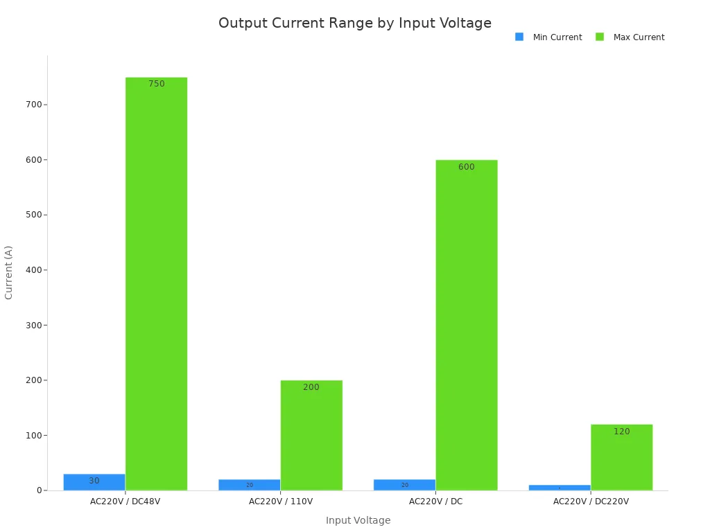
ESTEL makes outdoor telecom cabinets and power systems, including Telecom Rectifier Systems. When you pick a system that can grow, look for hot-swap modules, N+1 redundancy, and a controller that supports remote monitoring. The rack size matters too. Common sizes are 1U, 2U, 3U, and 6U. These fit standard 19-inch racks. The table below shows input voltage choices and output current ranges.
Input Voltage | Output Current Range |
|---|---|
AC220V / DC48V | 30–750A |
AC220V / 110V | 20–200A |
AC220V / DC | 20–600A |
AC220V / DC220V | 10–120A |
Common output currents you can pick include 20A, 30A, 40A, 50A, 60A, 80A, 90A, 180A, 210A, and 330A. Your system must give steady DC48V output with efficiency above 96%. Look for grounding protection with a copper bar and a flexible cable inlet. Single-phase (120V/240V AC) and three-phase (220V/380V AC) choices fit many power setups.
Planning capacity and growing in steps
Plan your capacity in steps. Figure out your current load plus battery charging demand. Then size for N+1.
Example: A 100kVA load may use five 20kVA modules with one spare. This gives fault-tolerant backup.
Study your current and future load curves. Expect growth of 10-20% per year. Plan module additions in steps that match that growth. Use vertical expansion (adding modules in the same frame) and horizontal expansion (paralleling more frames). This lets you grow without downtime. Do not oversize, which wastes money and lowers efficiency. Do not undersize, which stresses parts. Make sure every module supports hot-swap under full load. This step-by-step approach matches your budget to your real load. You spend only when you need the power. ESTEL's Telecom Rectifier Systems give you a platform you can trust for years of growth.
Modular expansion design removes the hard choice between adding capacity and keeping your network live. Hot-swap modules let you swap units without any shutdown. N+1 redundancy means one module can fail without stopping the system. Controller-based monitoring helps you plan growth before you run out of power. You experience fewer maintenance windows and lower truck-roll and overtime costs. Your power supply tracks your actual load growth. As 5G network densification and edge computing push power demands higher, steady DC output becomes critical. Scalability without shutdown becomes a basic requirement, not an extra-cost feature. Check your current rectifier headroom today and confirm your system supports hot-swap modules and N+1 redundancy. Always plan your next expansion before you run out of capacity. This step protects your network from costly downtime.
FAQ
What is N+1 redundancy and how does it protect my site?
N+1 means you put in one more rectifier module than your load requires. If one module breaks, the other units handle the whole load. Your site keeps running with no break.
Can I add new modules to a running system without turning it off?
Yes. Hot-swap design lets you slide a module into an open slot while the system powers your load. The controller spots the new module and shares the load evenly. No outage needed.
Does the controller balance load when I mix module sizes?
Yes. The system controller spreads current across all active modules, no matter their individual ratings. It adjusts in real time to keep each module inside its safe operating range.
What input power sources does a modular rectifier system accept?
The system takes AC220V single-phase or 380VAC three-phase. It changes input to steady DC48V output. This flexibility fits utility grids, generators, and mixed-source sites.
See Also
Guaranteeing Dependable Electrical Power for Telecom Cabinet Systems
Calculating Telecom Cabinet Power Systems and Battery Requirements
Grid-Tied Solar Inverter With Battery System for Telecom Cabinets
Essential Knowledge About Telecom Power Supply Feature Sets
Solar Energy Storage System Designed for Telecom Cabinet Power
CALL US DIRECTLY
86-13752765943
3A-8, SHUIWAN 1979 SQUARE (PHASE II), NO.111, TAIZI ROAD,SHUIWAN COMMUNITY, ZHAOSHANG STREET, NANSHAN DISTRICT, SHENZHEN, GUANGDONG, CHINA
