Improving Telecom Cabinet Rectifier Module Efficiency through Topology and Heat Dissipation Optimization


You need to enhance rectifier module efficiency in telecom cabinets by focusing on both advanced electrical design and effective thermal management. High efficiency in telecom rectifiers reduces energy costs, lowers carbon emissions, and supports reliable power delivery. Modern telecom systems now achieve up to 98.5% efficiency using Class 4 rectifier modules and advanced semiconductor devices. The table below shows the latest efficiency statistics in telecom rectifier modules:
Metric | Value |
|---|---|
Total telecom rectifier modules deployed | |
Current efficiency of rectifier modules | Approximately 97% |
Future efficiency target | Up to 98% or 98.5% |
Optimizing heat dissipation and thermal management in advanced telecom systems improves uptime and reduces operational expenses in power systems.
Key Takeaways
Choose high-efficiency rectifier modules to reduce energy loss, lower heat generation, and save operational costs.
Optimize heat dissipation using modular heat sinks, advanced cooling methods, and smart placement to prevent overheating and extend equipment life.
Use advanced semiconductor devices like GaN and low-RDS(on) MOSFETs to improve switching speed, reduce power loss, and enhance reliability.
Select efficient rectifier topologies such as bridgeless totem-pole PFC designs to achieve over 98% efficiency and better power quality.
Follow proper installation and maintenance steps, including regular cleaning and monitoring, to sustain peak performance and avoid common efficiency losses.
Efficiency Importance
Energy Efficiency Impact
You play a crucial role in shaping the future of telecom power systems by focusing on energy efficiency. When you select high efficiency rectifier modules, you maximize power conversion and minimize energy loss. Advanced technologies such as CoolGaN™ and CoolSiC™ enable rectifiers to reach over 99% efficiency at half load. This improvement saves about 20% energy during power conversion and reduces repair costs because these modules last over 1,000,000 hours. You protect sensitive telecom hardware by maintaining stable voltage and current, which ensures uninterrupted service for growing demands like 5G.
High efficiency rectifiers convert AC power to DC power with minimal loss.
You lower operational costs and extend equipment lifespan.
Stable power output shields telecom equipment from voltage fluctuations.
Energy-efficient solutions support renewable energy integration, advancing energy optimization.
ESTEL rectifier modules use silicon carbide components to minimize heat and power wastage. These modules achieve a peak efficiency rating of 97.83% at 277 Vac. You benefit from reduced energy consumption and reliable performance, even under variable conditions. This approach supports sustainability and enhances overall system performance.
Operational and Environmental Benefits
You improve telecom operations by choosing rectifiers with high efficiency ratings. These modules cut power loss by up to 75% compared to older designs. Lower heat generation reduces cooling energy needs, which further decreases carbon emissions. Active power factor correction boosts power usage and reduces losses. You can integrate renewable energy sources, such as solar and wind, to lower your carbon footprint.
Feature/Metric | Description/Impact |
|---|---|
Rectifier Efficiency | Up to 97-98% efficiency in AC to DC power conversion, minimizing energy loss |
Power Loss Reduction | Power loss cut by as much as 75% compared to older rectifiers |
Heat Generation | Lower heat output reduces cooling energy needs, further cutting emissions |
Power Factor Correction (PFC) | Active PFC improves power factor to 0.95-0.99, optimizing power usage and reducing losses |
Renewable Energy Integration | Supports solar and wind, enabling cleaner energy use and lowering carbon footprint |
Deployment Scale | Around 2.4 million modules deployed with near 97% efficiency, amplifying impact |
The GreenConnect project showed a 30% reduction in energy consumption and a 40% decrease in CO2 emissions after installing high efficiency telecom rectifiers at 500 remote sites. You drive sustainability and operational excellence by adopting energy-efficient solutions in telecom systems.
Rectifier Module Topology

Topology Options
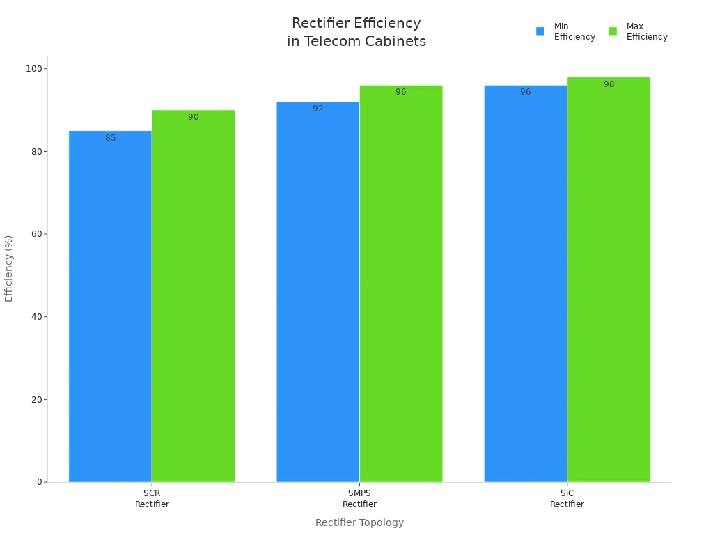
You have several rectifier topologies to choose from when designing high-efficiency telecom rectifiers. Each topology offers unique advantages for telecom applications, impacting both efficiency and performance. The table below summarizes the most common rectifier topologies, their typical efficiency ranges, and where you might use them in telecom systems:
Rectifier Topology | Typical Efficiency Range (%) | Common Telecom Applications |
|---|---|---|
SCR (Silicon Controlled Rectifier) | 85–90 | Central offices, legacy telecom systems |
SMPS (Switch Mode Power Supply) | 92–96 | Modern base stations, remote telecom cabinets |
SiC (Silicon Carbide) Rectifiers | 96–98 | High-performance rectifiers, 5G telecom sites |
You can also select from a range of rectifier designs, including:
Half-wave rectifiers: Simple, low efficiency, best for low-power telecom applications.
Full-wave rectifiers: Use both halves of the AC waveform, offering higher efficiency and smoother DC output.
Bridge rectifiers: Compact, efficient, and widely used in high-power telecom rectifier modules.
Single-phase rectifiers: Suitable for moderate power telecom systems.
Three-phase rectifiers: Reduce ripple, improve efficiency, and support high-power telecom cabinet modules.
Bridgeless power factor correction (PFC) topologies, such as the totem-pole design, have become popular in high-efficiency telecom rectifier modules. These topologies eliminate the diode bridge, reducing conduction losses and improving overall performance. You achieve superior efficiency and power density, especially when you combine these designs with advanced semiconductor devices.
Maximum Efficiency Designs
You can maximize efficiency in telecom rectifier modules by adopting advanced design features and integrating rectifiers with converters. Bridgeless totem-pole PFC topologies stand out for their ability to reduce both conduction and switching losses. By removing the diode bridge, you avoid voltage drops that typically waste power. For example, a traditional 4-kW bridge PFC dissipates about 33 W in the diode bridge, resulting in a significant efficiency loss. Bridgeless totem-pole PFC designs can reach efficiencies above 98.6%, meeting the strictest 80 Plus Titanium standards.
Tip: Bridgeless totem-pole PFC topologies use a single inductor for the full AC cycle, which increases power density and reduces the size of your telecom rectifier module.
At lower power levels, switching losses dominate, so both bridgeless and traditional boost PFC topologies perform similarly. As you scale up to higher power, the bridgeless totem-pole design delivers much higher efficiency. This topology also operates in continuous conduction mode (CCM), which reduces current ripple and total harmonic distortion, improving power quality and reducing the size of input filters.
Integrating rectifiers and converters in a single telecom rectifier module further minimizes power loss. The table below highlights the operational impact of these integration strategies:
Efficiency Improvement | Operational Impact | Explanation / Benefit |
|---|---|---|
Reduced energy losses and operational costs | Higher efficiency reduces wasted power, lowering electricity bills and cooling needs | |
98% reduction in battery failure rate (2018-2024) | Improved network reliability and uptime | Fewer battery failures mean less downtime and better service availability |
20% improvement in network uptime | Enhanced service availability | More reliable network operation with less downtime |
25-35% reduction in operational costs | Lower total cost of ownership | Savings from energy efficiency and hybrid power integration |
Modular, plug-and-play designs | Scalability and easier maintenance | Enables rapid scaling and maintenance without service disruption |
Up to 50% downtime reduction via AI and IoT predictive maintenance | Optimized performance and reduced maintenance costs | Predictive management reduces unexpected failures and maintenance time |
>90% efficiency with 20-30% energy savings and up to 40% CO2 emission reduction | Environmental sustainability | Supports regulatory compliance and corporate responsibility |
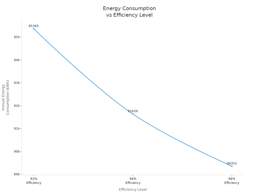
Upgrading your telecom rectifier modules from 92% to 98% efficiency can save over 6,000 kWh per year for a 10 kW load. These savings translate into lower heat generation, reduced cooling requirements, and extended equipment lifespan. You also benefit from shorter payback periods and improved sustainability.
Advanced Semiconductor Devices
You can achieve superior efficiency and performance in telecom rectifiers by leveraging advanced semiconductor devices. Gallium Nitride (GaN) and low-RDS(on) MOSFETs have revolutionized rectifier module design. GaN devices offer higher electron mobility, wider bandgap, and greater breakdown voltage than silicon. These properties enable faster switching speeds and lower gate charge, which reduce both conduction and switching losses. As a result, GaN-based rectifier modules operate at higher frequencies, allowing you to use smaller passive components and achieve better thermal performance.
Low-RDS(on) MOSFETs further reduce conduction losses in synchronous rectification. These devices maintain high maximum drain current and a safe operating area, ensuring reliability even under high current surges. Advanced packaging, such as LFPAK56 and copper-clip construction, improves thermal stress absorption and reliability in telecom rectifier modules.
Feature | Description |
|---|---|
Low RDS(on) | Reduces conduction (I²R) losses, improving efficiency in synchronous rectification and other power applications. |
High Maximum Drain Current (ID(max)) | Up to 380 A continuous current capability, important for high-current and fault-tolerant applications like motor control. |
Safe Operating Area (SOA) | Maintained without compromise, ensuring ruggedness and reliability under high current surges. |
Package Technology | LFPAK56 and LFPAK33 with copper-clip construction for better thermal stress absorption and reliability. |
Applications | ORing, hot-swap operation, synchronous rectification, motor control, battery protection, mobile fast-charge, DC load switch. |
You gain several advantages by using GaN devices in telecom rectifier modules:
Lower switching and conduction losses compared to silicon and SiC, resulting in reduced power loss.
Operating temperatures 40-60°C lower than silicon, which directly reduces heat generation.
Support for bridgeless totem-pole topologies, eliminating forward voltage drop and reverse recovery charge of input bridge rectifiers.
Smaller heat sinks and magnetics, leading to compact, lightweight telecom rectifier modules.
Three times less switching loss and about 1% higher efficiency in synchronous buck converters.
Superior thermal performance and innovative packaging, such as GaNPX, further reduce system heat dissipation and increase reliability.
You ensure maximum efficiency and reliability in your telecom rectifiers by selecting advanced semiconductor devices and optimized topologies. This approach supports high-performance telecom systems, reduces operational costs, and meets the growing demand for sustainable, high-efficiency telecom rectifier modules.
Heat Dissipation Optimization

Effective heat dissipation optimization is essential for maintaining high efficiency and reliable performance in telecom cabinet rectifier modules. You need to select the right cooling strategies and thermal management solutions to handle increasing power densities and prevent overheating. By focusing on advanced cooling systems, modular heat sinks, and liquid cooling advances, you can ensure optimal heat dissipation and system longevity.
Cooling Methods
You have several cooling methods available to manage heat in high-power telecom rectifier modules. Fan cooling with speed controls is a popular choice. This method efficiently removes heat while keeping noise levels low. Fan cooling supports hot-pluggable connectors, which adds flexibility and durability to your system. You can rely on this approach for consistent performance, even in challenging environments.
Thermoelectric air conditioners (TEC) offer another advanced cooling solution. These solid-state devices transfer heat from inside the cabinet to the outside without moving mechanical parts. TECs use Peltier modules powered by direct current to move heat, while heat sinks and fans on both sides enhance heat dissipation. You benefit from precise, silent, and maintenance-free cooling, making TECs ideal for telecom shelters and battery enclosures that require strict temperature control.
Passive convection cooling also plays a role in heat dissipation. Systems like IP65-rated enclosures use ribbed surfaces to increase the area for heat dissipation. This method eliminates the need for fans or filters, reducing maintenance and ensuring dust and water resistance. You can deploy these systems outdoors with confidence, knowing they will lower maintenance costs and extend product life.
Tip: Choose the cooling method that matches your power density and environmental conditions. Combining active and passive cooling often delivers the best results for high efficiency and reliability.
Modular Heat Sinks
Modular heat sinks provide a scalable and flexible approach to heat dissipation in telecom cabinet rectifier modules. You can adapt your system to varying power demands by adding or removing heat sink modules as needed. This modularity increases the surface area for heat dissipation and improves heat spreading in compact, high-density environments.
You gain several advantages with modular heat sinks:
Scalable power capacity to match changing requirements.
Enhanced heat dissipation through increased surface area and better heat spreading.
Easy maintenance and upgrades, reducing downtime and preserving efficiency.
Integration with advanced thermal management features such as high thermal conductivity substrates, thermal vias, and real-time temperature monitoring.
Prevention of overheating, which is critical for maintaining high efficiency and reliable operation.
Compatibility with advanced cooling systems like miniature fans or thermoelectric coolers for added thermal stability.
Efficient use of space in compact telecom cabinets.
Optimized heat sink designs further improve heat dissipation. For example, replacing standard heat sinks with patented maxiFLOW™ models and offsetting them to create linear airflow can keep junction temperatures well below maximum limits. Analytical and CFD modeling confirm that these solutions maintain safe operating temperatures, improve reliability, and offer cost-effective alternatives to more complex heat pipe systems.
Aspect | Details |
|---|---|
Challenge | Cooling a telecom PCB with airflow possible from either direction; two high-power components on opposite sides |
Solution | Offset, optimized heat sinks (e.g., maxiFLOW™) create linear airflow and achieve required thermal performance |
Outcome | Maintained junction temperatures below max limits, improved reliability, and cost-effectiveness |
Placement strategies play a crucial role in maximizing the effectiveness of modular heat sinks. You should space high-power components to avoid concentrated heat zones and place heat-generating parts close to heat sinks for direct dissipation. Aligning components with airflow paths enhances both natural and forced convection cooling. Positioning thermal vias under or near heat sources spreads heat evenly through PCB layers, while copper pours act as heat spreaders to reduce thermal resistance. Using thermal simulation tools helps you optimize component and heat sink placement, preventing hotspots and ensuring efficient heat dissipation.
Distribute heat sources to prevent localized hotspots.
Place high thermal dissipation components near heat sinks or in optimal airflow areas.
Use modular heat sinks for scalable thermal design.
Integrate active and passive cooling with placement strategies for maximum efficiency.
Liquid Cooling Advances
Liquid cooling represents a significant advancement in thermal management for high-power telecom cabinet rectifier modules. You can achieve much higher efficiency and reliability with liquid cooling, especially in dense or high-load environments where air cooling may fall short. Liquid cooling systems use advanced materials such as multifunctional phase change composite films and microencapsulated phase change materials. These materials provide sub-ambient cooling, high latent heat capacity, and excellent thermal stability, supporting both passive and active thermal management.
Material / Study | Key Thermal Performance Metrics | Application Context |
|---|---|---|
Multifunctional Phase Change Composite Film (MPCCF) | Sub-ambient cooling by 7.0 °C under solar irradiance | All-climate thermal management for power converters |
Al-Si@Void@SiO2 MEPCMs | Latent heat capacity of 454.9 J/g, 90.7% encapsulation efficiency | High temperature thermal energy storage |
SnBi58@Void@TiO2 MEPCMs | Heat storage density of 496 J/g, durability over 1300 cycles | High temperature thermal energy storage |
Paraffin/Olefin Block Copolymer in Expanded Graphite (FPCM) | Improved thermal conductivity | Battery and power module management |
Ceramic Shape-Stabilized PCMs (SSPCM) | High latent heat and thermal conductivity | Next-generation thermal management |
Liquid cooling systems, especially those using water, can deliver three to four times the cooling efficiency of traditional air cooling. Industry leaders report that liquid cooling reduces cooling energy consumption by up to 35%, which directly improves energy efficiency and extends equipment lifespan. You benefit from stable temperatures under heavy loads, which enhances performance and reliability. However, liquid cooling systems require pumps, heat exchangers, and regular maintenance, making them more complex and costly than air cooling. Despite these challenges, liquid cooling is ideal for high-power, high-density telecom rectifier modules that demand consistent thermal management.
Aspect | Air Cooling (Active Cooling) | Liquid Cooling (Active Cooling) |
|---|---|---|
Efficiency | Suitable for low to medium heat dissipation needs; less efficient at high heat loads | More efficient at removing heat, especially in high-power applications |
Complexity & Cost | Lower initial cost and maintenance; simpler design | Higher initial cost and maintenance due to pumps, heat exchangers |
Temperature Control | Limited precision; depends on ambient airflow | Precise temperature control, maintains stable operating conditions |
Reliability | Easier maintenance, fewer components to fail | Requires regular maintenance but prevents overheating, extending equipment lifespan |
Application Suitability | Best for low to medium power telecom rectifier modules | Ideal for high-power, high-density telecom rectifier modules requiring stable thermal management |
You should evaluate your application’s power density, space constraints, and reliability requirements before choosing between air and liquid cooling. For most high efficiency telecom rectifier modules, combining modular heat sinks with advanced cooling systems and strategic placement delivers the best balance of performance, efficiency, and cost.
Implementation Steps
Integration Best Practices
You achieve optimal efficiency in high-efficiency telecom rectifier installations by following proven integration steps. Begin by powering down the system and disconnecting all cables. Confirm no residual voltage with a multimeter for safety. Verify the compatibility of each rectifier module and inspect cable connections to avoid installation errors. Mount the telecom rectifier module with enough clearance to support effective cooling and thermal management. Configure system settings according to manufacturer guidelines to ensure correct operation. After installation, perform a test run to monitor performance and detect irregularities. Maintain cleanliness inside the cabinet to prevent dust buildup, which can degrade components and reduce efficiency. Regularly inspect and replace worn-out parts such as capacitors, fans, and connectors. Always use manufacturer-approved procedures and proper tools to minimize risks.
Tip: Use high-quality cables rated for maximum current to minimize power losses. Secure all connections tightly and organize cables to simplify maintenance and reduce accidental disconnections. Proper grounding protects telecom rectifiers and maintains stable power delivery.
Step | Purpose |
|---|---|
Power down and disconnect | Ensures safety during installation |
Verify compatibility | Prevents installation errors |
Mount with clearance | Supports cooling and thermal management |
Configure settings | Ensures correct operation |
Test run | Monitors performance and detects issues |
Clean cabinet | Prevents dust-related losses |
Inspect and replace parts | Maintains reliability and efficiency |
Use proper procedures/tools | Minimizes risks and errors |
Maintenance for Efficiency
You sustain peak efficiency and performance in telecom rectifiers by implementing a robust maintenance routine. Turn off power before cleaning. Use a soft brush or compressed air to remove dust from vents and internal components. Inspect for signs of wear, such as discoloration or corrosion, and address damage immediately. Monitor voltage and current levels regularly with multimeters or computerized systems to detect irregularities early. Tighten or clean all electrical connections to prevent power losses. Update firmware and software to improve functionality and security. Schedule cleaning every three to six months, increasing frequency in dusty or humid environments. Control temperature and humidity with cooling systems and dehumidifiers to prevent thermal damage. Use high-quality replacement parts to extend the lifespan of telecom rectifier modules. Leverage monitoring tools and analytics for predictive maintenance, enabling early detection of issues and reducing downtime. Provide comprehensive training for maintenance personnel to ensure best practices.
Avoiding Common Mistakes
You protect efficiency and reliability in telecom rectifier module installations by avoiding frequent mistakes:
Improper firmware or software updates can cause malfunctions and reduce efficiency.
Neglecting cooling system maintenance leads to overheating and increased power losses.
Failing to clean and remove dust impairs cooling and shortens component lifespan.
Loose or corroded electrical connections increase resistance, causing power interruptions and losses.
Insufficient inspection and tightening of connections risk overheating and failures.
Note: Neglected cooling fans can raise energy costs by up to 25%. Regular cleaning, securing connections, and timely updates are essential for maintaining high efficiency and performance in telecom systems.
You can achieve maximum efficiency in telecom rectifiers by following these strategies:
Select high-efficiency rectifiers to reduce energy loss and heat.
Implement advanced heat dissipation with modular heat sinks and real-time temperature monitoring.
Use digital control for adaptive regulation and remote diagnostics.
Ensure compliance with telecom standards for safety and reliability.
Choose scalable, modular designs for easy maintenance and future upgrades.
Adopting advanced telecom rectifiers with wide bandgap semiconductors and smart monitoring improves energy efficiency, lowers operational costs, and supports sustainability. Many telecom operators have reported up to 40% lower energy consumption and improved reliability after upgrading their systems.
Stay proactive by monitoring your telecom rectifiers and adapting to new efficiency solutions as technology evolves.
FAQ
What is the main benefit of using GaN devices in telecom rectifiers?
You gain higher efficiency and lower heat generation with GaN devices. These semiconductors switch faster and waste less energy than traditional silicon. You also reduce the size of heat sinks and improve overall system reliability.
How often should you clean telecom rectifier modules?
You should clean your rectifier modules every three to six months. In dusty or humid environments, increase the frequency. Regular cleaning prevents dust buildup, which can cause overheating and reduce efficiency.
Can you combine air and liquid cooling in one telecom cabinet?
Yes, you can combine both methods. Air cooling handles moderate heat loads, while liquid cooling manages high-density or high-power areas. This hybrid approach gives you better temperature control and extends equipment lifespan.
What causes hotspots in telecom cabinets?
Hotspots form when you place high-power components too close together or block airflow. Poor heat sink placement also leads to uneven cooling. Use thermal simulation tools to optimize layout and prevent these issues.
How do you know if your rectifier module is running efficiently?
You should monitor voltage, current, and temperature regularly. Use built-in diagnostics or remote monitoring tools. If you notice abnormal readings or increased energy use, inspect the system for dust, loose connections, or cooling failures.
See Also
Exploring Various Cooling Techniques Used In Telecom Cabinets
Steps To Guarantee Consistent Power For Telecom Cabinets
Maintaining Ideal Temperature Levels In Outdoor Telecom Cabinets
Selecting The Most Effective Cooling Option For ESTEL Cabinets
Using Solar Energy Storage Systems To Power Telecom Cabinets
CALL US DIRECTLY
86-13752765943
3A-8, SHUIWAN 1979 SQUARE (PHASE II), NO.111, TAIZI ROAD,SHUIWAN COMMUNITY, ZHAOSHANG STREET, NANSHAN DISTRICT, SHENZHEN, GUANGDONG, CHINA