How to Achieve Redundancy in a 48V Telecom Power System


You can achieve redundancy in a 48V telecom power system with four practical steps. First, determine the total load and add room for growth. Second, choose your redundancy level, either N+1 or 2N. Third, size rectifiers and batteries to that level. Fourth, validate distribution and monitoring. Redundancy means extra capacity, so a single failure does not interrupt the load. The 48V DC architecture is the standard for telecom sites. This guide gives you a step-by-step method with simple rules of thumb. You will size your system confidently, without over-engineering or overspending.
Key Takeaways
Calculate total load and add 25% for growth to plan capacity.
Choose N+1 redundancy for most sites; use 2N for critical ones.
Size rectifiers to keep normal load at or below 80% of capacity.
Design separate A and B power paths for true redundancy.
Monitor alarms and trend load yearly to catch failures early.
Step 1: Determine Load for Your Telecom Power System
Calculate Current DC Load
A telecom power system converts incoming AC into regulated −48V DC. It supplies the load while it charges the battery bank. The nominal -48 v dc architecture uses a positive-ground design, and engineers build it from 12V cells. The 48V level stays within extra-low voltage safety limits, so technicians can work on it with standard precautions. This is why the telecommunications power system standard settled on 48V.
Start with each piece of equipment's power rating in watts. Divide that rating by the nominal 48V to get current in amps. A 2,000W radio unit draws about 42A at 48V. Sum every load this way, and you have the continuous dc load. Add the peak current that transient events demand, because startup surges and busy-hour traffic push draw above the steady value. Record both figures in your dc load profile. The continuous and peak load numbers become the foundation for every later decision.
Apply a Growth Factor
Multiply your total load by a growth factor of 1.25. This step covers future expansion and keeps your capacity planning honest. A site that draws 100A today needs a design target of 125A. That margin feeds directly into rectifier sizing and redundancy choices later.
Track the dc load profile over time, and update it as you add equipment. Two capacity decisions depend on this number: how many rectifier modules you install and how much battery autonomy you buy. A realistic maximum site current keeps your dc power system efficient. Most dc power systems fail at this stage because nobody revisits the load list. Recheck the load list each year. Ignore growth, and you risk peak current and redundancy gaps within a year or two.
Step 2: Choose Your Redundancy Configuration
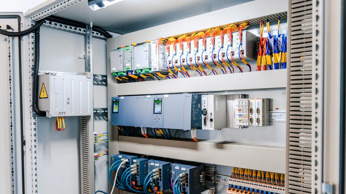
N+1 vs. 2N Trade-Offs
N+1 means you install N units to carry the full load plus one spare. A single module can fail or go into maintenance, and the site keeps running. 2N means two independent sets, each able to carry the full load alone. One entire set can go down without touching service. The table below compares the two configurations on the dimensions that matter most.
Dimension | N+1 | 2N |
|---|---|---|
Reliability | One spare covers a single failure; shared circuitry can still cause outages; typical uptime ~99.982% | Full duplication of components and paths; no single point of failure; typical uptime ~99.995% |
Cost | Moderate capital cost; lower energy use | High capital and operational cost; doubles infrastructure; higher energy consumption |
Operational Complexity | Simple, incremental expansion; easier management | Complex implementation; higher space requirements |
The trade-off is straightforward. N+1 balances reliability and cost, and it suits sites where failure risk is low to moderate. 2N duplicates the whole arrangement, so it survives multiple failures and full maintenance downtime. That protection costs roughly double the infrastructure and consumes more energy, because dual-path operation lowers efficiency. Redundancy always trades money for uptime, and your job is to pick the point where that trade pays off.
Match Redundancy to Site Criticality
Map each site to a tier before you commit. Core nodes carry heavy traffic and serve many users, so they justify 2N or even 2(N+1). Edge sites sit between core and access, and most of them run well on N+1 parallel redundant rectifiers. Remote sites with light traffic and long maintenance cycles usually fit N+1 as well, provided you verify battery autonomy and alarm coverage.
N+1 parallel redundant rectifiers cover about 90% of standard critical tasks, according to industry guidance, at lower module count, installation effort, and energy cost than fully redundant systems. That makes N+1 the sensible default for most telecom sites. Reserve 2N for mission-critical continuity, where an outage is unacceptable and maintenance windows cannot interrupt service.
Size your capacity around this decision. A site designed for 125A of load needs enough parallel-redundant rectifiers to carry that load plus one spare module. The same logic applies to point-of-use n+1 redundant rectifier systems in smaller enclosures. Check peak current and redundancy together, because a surge can exceed the spare module's headroom. Many dc power systems look adequate on paper until a peak current event exposes the gap. Review your dc power system design against the load profile each year, and confirm that parallel rectifiers still match the site tier. This discipline keeps capacity honest and prevents both over-engineering and hidden single points of failure.
Step 3: Size Rectifiers and Batteries
Rectifier Capacity and Redundancy
Size rectifiers to your chosen redundancy level, then keep normal operating load at or below roughly 80% of installed capacity. Telcordia engineering principles support this threshold for DC power plants in telecom systems. The remaining margin supports voltage stability, battery recharge, and long-term network reliability. A site with a 125A design target therefore needs installed rectifier capacity near 156A, split across modules so one spare always stands ready.
Modular platforms make this easy to scale. ESTEL's Telecom Power System accepts 90–300 Vac input, uses natural cooling, mounts on a 19-inch rack or inside a cabinet at 2U height, delivers up to 150A output, and offers multiple communication ports. You add modules as the load grows, and the platform supports redundant configurations without a full rebuild. Check that your spare module covers peak current, not just steady draw. Many dc power systems look fine on paper until a surge exposes the gap.
Battery Runtime Under Real Loads
Battery sizing starts with your autonomy target, the hours the site must ride through an outage. Calculate runtime under real loads with a simple relation: runtime in hours = (capacity in Ah × system voltage × efficiency) ÷ load in watts. A 48V 200Ah battery bank at 90% efficiency feeding a 1,000W load gives 8,640 Wh of usable energy and about 8.6 hours of runtime. That figure is theoretical, so derate it before you commit.
Apply three corrections. Aging: plan for end of life at about 80% of rated capacity, which means a factor of 1.25. Temperature: capacity drops below 25 °C, and some VRLA batteries lose 20–30% at 0 °C. Depth of discharge: lead-acid gives roughly 50% usable capacity, while lithium iron phosphate reaches up to 90%. A cold outdoor site with a short high-rate discharge may need a combined derating factor of 0.6–0.7, so a nominal 15 minutes becomes roughly 9–10.5 minutes in design.
Set your required autonomy from site criticality, then confirm the dc system battery requirement against manufacturer discharge curves. Oversizing raises capital cost. Undersizing risks insufficient backup when the load peaks. Build runtime and capacity margins into the design, and treat the telecom tower battery bank as a living asset. Modular parallel battery banks let you add strings later, and they keep the required runtime intact when one string goes offline. Review runtime and capacity margins yearly, because load growth quietly erodes both.
Step 4: Design Distribution and Monitoring for Redundancy
Redundant Distribution Paths
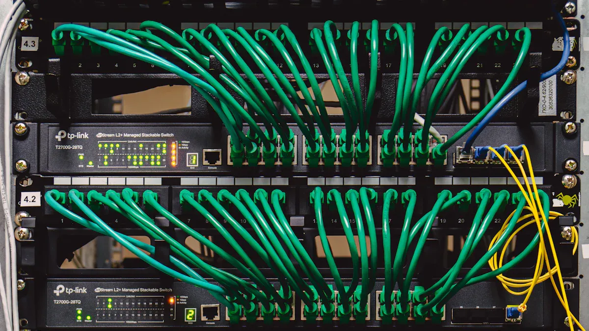
Redundancy stops at the rectifier unless the distribution matches it. Run separate A and B paths through independent switchboards, PDUs, RPPs, and feeders. Feed dual-corded equipment from both paths, so one path failure leaves the other supplying the load. Keep the paths truly independent: electrical separation, physical routing, protection coordination, maintenance procedures, and control systems all matter. Redundancy is not the same as fault tolerance, and shared conduit or a common terminal block quietly defeats both.
Coordinate breakers so a fault trips the nearest device only. A power shelf can feed two or more fuses or breakers, with the aggregated DC bus feeding the source side and the apparatus on the load side. Where two systems share one bus bar, connect each through its own breaker and avoid double-landing on a single chassis terminal block. In battery mode, place a two-pole breaker on the common bus upstream of both battery and equipment. This arrangement serves the load and the charge source together.
Monitoring That Protects Redundancy
Alarms turn redundancy into something you can verify. Cover the components that carry the critical load in your telecom power system:
Component | Monitored parameters |
|---|---|
Rectifier | DC output voltage, major alarm contact, failure status |
Battery plant | Voltage levels, charge status, individual string health |
DC distribution | Per-circuit voltage and fuse status |
Remote power monitoring is the continuous collection of power data, including AC and DC voltages, battery state, and rectifier and generator status, from unmanned sites, with automated alerts sent when readings go outside normal thresholds.
Trend the load over time, because slow growth erodes your spare module headroom. ESTEL's Telecom Power System offers multiple communication ports, so these signals integrate with your existing management platform. Well-instrumented dc power systems catch a failed rectifier before the next one goes. Review alarm coverage yearly across your dc power system, and confirm every critical circuit reports.
You now have a repeatable sequence: total load plus growth, redundancy level, rectifier and battery sizing, then distribution and monitoring. Right-size each step to site criticality. N+1 fits most sites, and 2N fits mission-critical continuity. This balance avoids over-engineering and hidden single points of failure.
Before you sign off, run a short validation pass:
Confirm rectifier loading stays at or below roughly 80% of installed capacity.
Verify battery runtime against your autonomy target with derating applied.
Check that alarms cover rectifier failure, battery health, and load trending.
Modular platforms such as ESTEL's Telecom Power System make future redundancy upgrades easier, because you add capacity without rebuilding the site.
FAQ
Is N+1 enough for my site?
For most telecom sites, yes. N+1 keeps the load running when one module fails or goes into maintenance. Reserve 2N for core nodes and mission-critical continuity, where an outage is unacceptable and maintenance windows cannot interrupt service.
How much spare rectifier capacity should I install?
Keep normal operating load at or below roughly 80% of installed capacity. That margin supports voltage stability, battery recharge, and long-term reliability. Size installed capacity to your design target plus one spare module, and confirm the spare covers peak current, not just steady draw.
Do I need redundant batteries too?
Not always. A single battery bank with healthy strings meets most N+1 sites. Where continuity is mission-critical, parallel battery banks let you add strings later and keep runtime intact when one string goes offline. Always derate runtime for aging, temperature, and depth of discharge.
Is 48V DC safe for technicians to work on?
Yes. The 48V level stays within extra-low voltage safety limits, so standard precautions apply. The architecture uses a positive-ground design and builds from 12V cells. That safety margin is a major reason telecom sites standardized on 48V DC.
How do I confirm redundancy still works after installation?
Run a yearly validation pass. Check rectifier loading against the 80% threshold, verify battery runtime against your autonomy target with derating applied, and confirm alarms cover rectifier failure, battery health, and load trending. Trend the load, because slow growth erodes your spare module headroom.
See Also
Ensuring Reliable Power Supply for Telecom Cabinets Effectively
Calculation Methods for Telecom Cabinet Power Systems and Batteries
Grid-Connected Photovoltaic Inverter and Battery System for Telecom Cabinets
Photovoltaic Energy Storage Power Systems for Telecom Cabinet Applications
CALL US DIRECTLY
86-13752765943
3A-8, SHUIWAN 1979 SQUARE (PHASE II), NO.111, TAIZI ROAD,SHUIWAN COMMUNITY, ZHAOSHANG STREET, NANSHAN DISTRICT, SHENZHEN, GUANGDONG, CHINA
