How to implement reverse current protection for batteries of Smart PDUs in telecom cabinets to prevent reverse charging during outages

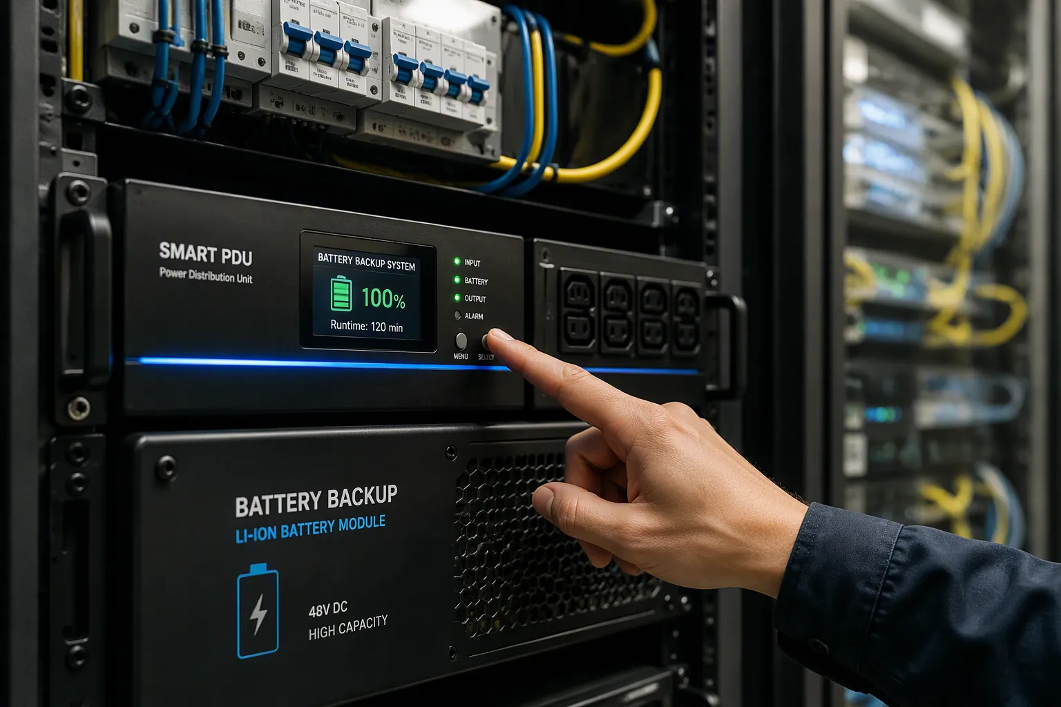
You stop reverse charging with one of three approaches in the battery path of a smart pdu: series blocking diodes, MOSFET-based ideal diode circuits, or active reverse current protection circuits. Each option blocks current from flowing back into the PDU during an outage. Each option also preserves normal discharge performance when the load draws on the battery. Series diodes suit simple, low-cost paths. MOSFET circuits cut conduction loss. Active circuits add fast, controller-driven response. These choices matter in telecom power supply systems, where backup integrity decides uptime. You will learn component selection, circuit design, integration into power distribution units, testing, and maintenance. The same principles apply across PDUs in telecom power supply systems and every dc branch. Modern telecom power supply designs reward careful protection planning, and dc faults punish shortcuts. Treat protection as a dc design decision, not an accessory.
Key Takeaways
Reverse charging can damage your PDU and drain batteries. Use protection to block reverse current.
Choose a series diode for simple, low-cost paths. Choose MOSFET or active circuits for higher efficiency.
Install the protection in the battery path inside the smart PDU. Size it for the discharge current and fault conditions.
Test the protection during a planned outage. Confirm it blocks reverse current and allows normal discharge.
Inspect and test protection regularly. Lock approved parts and repeat checks during drills to keep systems reliable.
Causes and risks of reverse charging in batteries
Reversed polarity and outage back-feed
Reversed polarity happens when you connect the positive and negative terminals incorrectly. This mistake can damage equipment when no protection exists. Common causes include installing a battery in the wrong orientation, using an incompatible adapter, making wiring errors during assembly, and mishandling connections. You can prevent this problem with polarized connectors, color-coded wires, and painted cues on non-polarized connectors.
Category | Cause or Protection Measure | Explanation |
|---|---|---|
Causes | Incorrect battery connection | Wrong orientation reverses polarity and damages the device |
Causes | Wiring errors during assembly | Power connection mistakes cause reversed polarity |
Protection | Polarized connectors | Physically prevent incorrect connections |
Protection | Series protection diode | Blocks current when anode voltage falls below cathode |
Outage back-feed is a separate risk. During a utility power failure, current from batteries can flow back into the charger or PDU supply rail. A diode in series with the supply rail blocks this reverse current. This protection keeps power flow in telecom systems moving in one direction only.
Failure modes in telecom cabinets
Reverse charging damages PDU circuitry and overheats components. It also drains battery energy, which shortens backup runtime when you need it most. In telecom battery backup systems, these failures compound quickly. A damaged rectifier or overheated board can take a whole cabinet offline.
Telecom dc power systems depend on clean one-way current. Reverse flow undermines dc power distribution across every branch. You protect dc power systems by addressing the fault path early. Proper protection in telecom power supply systems preserves both the PDU and the battery string. These safeguards matter in any dc telecom power system, and they keep dc bus conditions stable. Good design protects batteries, battery systems, and backup power alike. Smart PDUs and power distribution units benefit from the same measures. Reliable dc telecom power supply design starts with understanding these failure modes.
Choosing DC protection technology
Series diodes vs. MOSFET circuits
A series diode allows current in only one direction. It blocks reverse current from the battery back into the charger during an outage. The trade-off is forward voltage drop. A silicon diode drops about 0.7V, and a Schottky part drops roughly 1V at high current. That drop wastes power and limits load current at low input voltages. At high current, the dissipation needs a large, costly package comparable to a low-Rds MOSFET.
A reversed drain/source NMOS works as a low-Vf diode. It shows very little forward voltage drop and power dissipation, and a TO-220 case suffices. It is fast. It needs extra circuitry to drive it, though.
Method | Voltage Drop / Efficiency | Complexity | Grounding / Other Trade-offs |
|---|---|---|---|
Series diode | ~0.7V drop (silicon); wastes power, reduces efficiency especially at low voltages | Simplest | Blocks reverse current completely; simple but inefficient |
PMOS high-side | Very low resistance/drop; minimal loss, high efficiency | Moderate (needs Zener + resistor biasing) | Widely preferred; efficient |
NMOS low-side | Low resistance, high efficiency | Moderate (resistor + Zener gate control) | Shifts load ground reference slightly; may not suit sensitive circuits |
MOSFET-based circuits provide reverse voltage protection for battery chargers. A reverse-connected battery lifts the MOSFET source above its gate. That action turns the device off. This behavior gives you efficient dc protection with minimal loss.
Active reverse current protection
Active circuits use controller-driven FETs. They minimize conduction loss and provide fast reverse current protection. These dc protection devices suit 48v dc strings where efficiency matters. They also fit telecom power supply systems that need tight control.
Watch one limitation. The BQ2970 does not provide reverse battery protection. Its BAT pin cannot go negative, and its V- pin cannot rise above BAT. A reversed cell therefore sits outside the allowed operating conditions. A reverse-charge FET must stay on when the cell is properly connected. If the cell voltage drops below the FET's VGSTH, the FET behaves as a diode and charging is blocked. You need an external FET to handle a reversed cell, because the IC itself cannot.
Each option fits a different job. Series diodes suit simple, low-cost paths in telecom power supply systems. MOSFET circuits cut loss in 48v dc branches. Active circuits serve demanding telecom power supply designs. All three protect batteries and the dc bus. Choose by loss budget, complexity, and the isolation you need. Power isolation and clean dc power systems reward this planning. Smart pdus and other dc equipment benefit from the right match. Match the technology to the branch, and the protection holds.
Implementing protection in the smart PDU
Component selection and 48V DC design
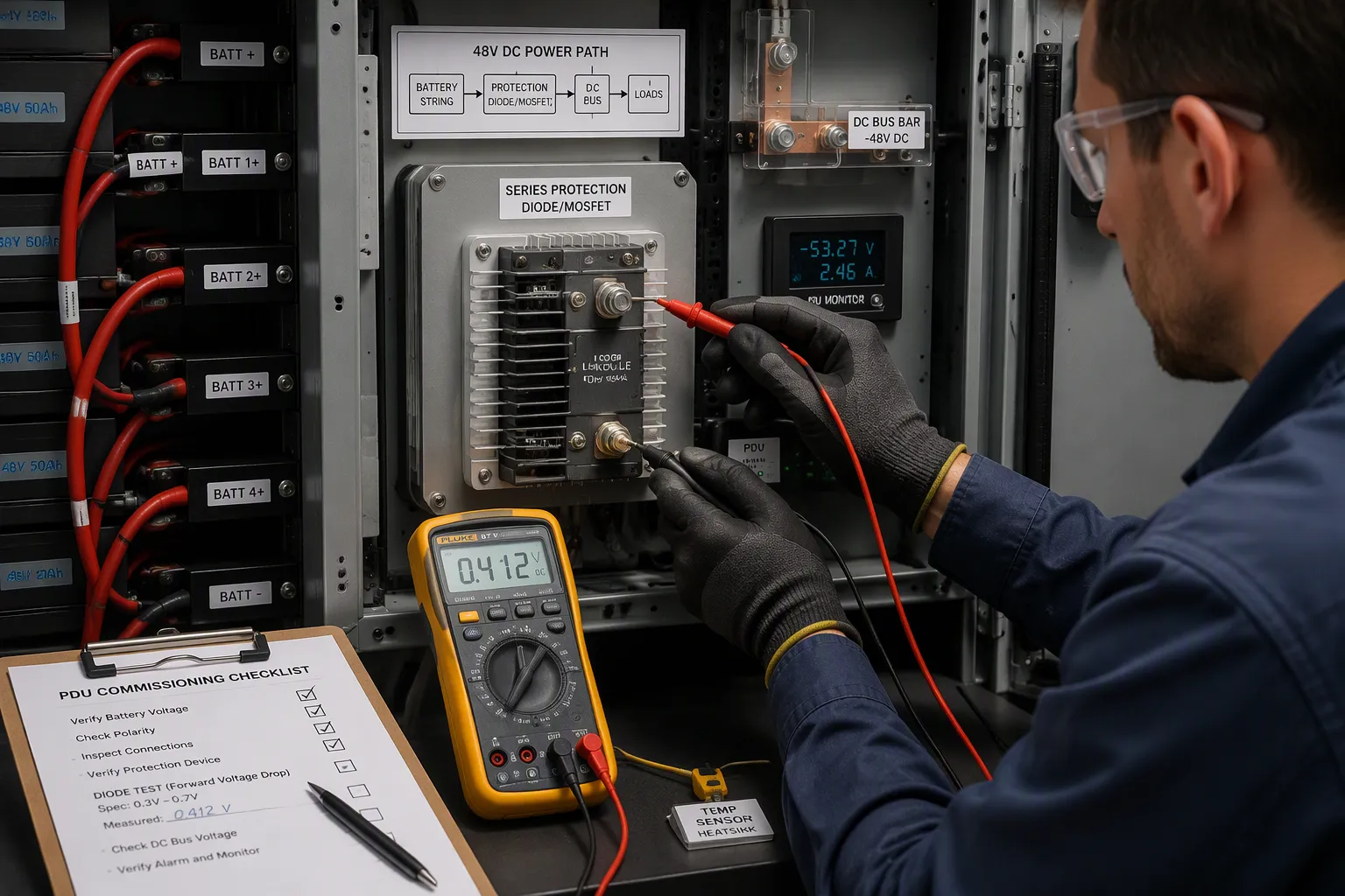
Size the diode or FET for the discharge current of the 48V DC battery string and for fault conditions. Check the continuous rating against the load the batteries carry during a utility power failure. Then check the surge rating against the short-circuit current the string can deliver. A part that survives normal discharge may still fail under a fault. Derate the part for cabinet temperature, because a sealed telecom cabinet runs warmer than a lab bench.
Parameter | What to Check | Why It Matters |
|---|---|---|
Continuous current | Diode or FET rating vs. battery discharge current | Prevents overheating during an outage |
Surge current | Fault current the 48V DC string can deliver | Prevents failure under short circuit |
Forward drop | Loss at rated current | Sets heat and efficiency in the 48V DC path |
Temperature derating | Rating at cabinet ambient | A warm cabinet lowers the safe current |
Place the protection in series with the battery path inside the smart PDU. This position blocks reverse current from the batteries into the supply rail. Consider DC-bus reverse polarity protection in the same way engineers treat PV-side schemes. The goal is the same: keep current flowing one way on the DC bus.
Integration, configuration, and testing
Wire the protection into the battery path of the smart PDU. Configure the thresholds so the PDU reacts before the 48V DC rail collapses. A smart PDU can automatically reduce battery load when voltage drops. That action extends battery charge during an outage. Combine this behavior with remote power systems for wider visibility.
Test the design during a planned outage. Confirm the protection blocks reverse current into the supply rail. Then confirm normal discharge is unaffected. Measure the drop across the part at rated current and compare it with your loss budget. Check the charge/discharge current path in both directions. A smart PDU makes this test easier, because you can log the DC bus voltage and current during the drill.
These steps apply to PDUs across telecom DC power systems. The same logic serves DC power systems in any cabinet. Protection belongs in the battery path of every unit you deploy. Power distribution units in a DC telecom power system share this requirement. Treat the 48V DC branch as the place where protection earns its keep. Good DC protection keeps battery systems healthy and backup power ready. It also keeps DC power distribution clean across the cabinet. A battery bank with proper protection survives a utility power failure without damage. Battery charging during normal operation continues untouched. That balance — blocked reverse flow, normal forward flow — defines success. Apply it to every 48V DC branch in your telecom power supply fleet. Your telecom power supply systems will reward the discipline. Telecom power supply designs that skip this step carry hidden risk. Telecom power supply systems in the field depend on it. Telecom DC power systems and every DC branch benefit. The DC bus stays stable, and the batteries stay protected.
Maintenance and long-term reliability
Inspection and periodic verification
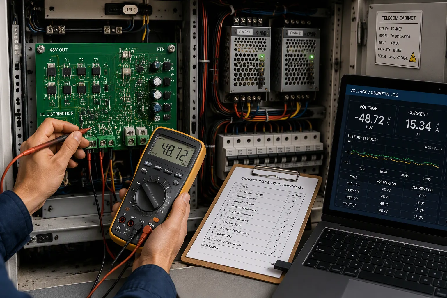
Schedule a visual inspection of every protection circuit in your cabinets. Check the body-diode orientation of each MOSFET during assembly and again during rework. Confirm that silkscreen markings stay clear and that approved part variants remain locked. Uncontrolled BOM substitutions quietly change fault behavior.
Treat a bench power-on as a starting point, not proof. Add reverse-input, hot-plug, thermal, low-battery, transient, and post-fault recovery tests to your design verification plan. Then repeat the key checks during routine outage drills. Verify that protection blocks reverse flow into the dc bus and that normal discharge stays unaffected. Log the dc bus voltage and current each time. This habit keeps telecom power supply systems honest across the fleet.
Common pitfalls and best practices
One common mistake assumes a low-loss MOSFET topology is automatically low-risk. Match the topology to the real system constraint, not to headline efficiency. Budget the protection circuit's standby loss and minimum operating voltage in the power budget. Review Rds(on) at the intended gate drive, the safe operating area under reverse and hot-plug transients, and package thermal performance in the actual layout.
In 2025–2026 independent lab reports, 40% of failed DO-160G transient tests in UAV power systems were caused by MOSFET protection circuits exceeding safe operating area limits during reverse-polarity spikes, whereas diode/fuse circuits passed 92% of the same tests — showing that under stress, fault behavior can outweigh steady-state efficiency gains.
Common Pitfall
Best Practice
Assuming a low-loss topology is low-risk
Match topology to the real constraint
Ignoring gate-protection leakage in standby
Budget standby loss and minimum voltage
Selecting parts on best-case datasheet lines
Review Rds(on), SOA, and thermal performance
Wrong body-diode orientation
Verify orientation during assembly and rework
Treating bench power-on as validation
Add reverse, hot-plug, and thermal tests
Uncontrolled BOM substitutions
Lock approved variants and alternates
Undefined fault behavior across teams
Align engineering, test, quality, and service
Follow a disciplined sequence for each new branch:
Define the fault model (battery swaps, field wiring errors, service harness mistakes, or controlled assembly only).
Set the power-path constraint — if the rail cannot tolerate meaningful drop, eliminate diode-only options early.
Choose the gate strategy carefully — a clamp that protects the MOSFET but drains battery life may still be wrong.
Review thermal and SOA margin — the most efficient part in steady state can still fail in short fault events.
Plan for sourcing and assembly — avoid topologies dependent on a single narrow-availability part.
Apply this discipline to batteries, 48v dc branches, and every 48v dc string you deploy. Good protection keeps batteries healthy through a utility power failure. It keeps 48v dc current flowing one way. It keeps dc power systems predictable. Smart pdus, power distribution units, and telecom power supply designs all share the requirement. Telecom power supply systems and telecom dc power systems reward the routine. Batteries last longer, and the dc bus stays stable. Telecom power supply teams that inspect, test, and document will catch faults before an outage does.
Follow four steps in order. First, identify the reverse-charging path in the battery branch. Second, select the protection technology for that branch. Third, design and integrate the circuit into the smart pdu. Fourth, test and maintain it.
Good protection shields both the PDU and the batteries. Skipping tests or maintenance weakens the design. Verify blocking behavior during routine outage drills. That habit keeps your dc power systems ready. It also keeps dc current flowing one way. Your pdus, battery strings, and dc branches all depend on it. Telecom power supply systems reward the routine. Telecom power supply teams that drill will catch faults early. Telecom power supply designs stay honest. Telecom power supply fleets stay reliable. Telecom power supply practice improves with every drill.
FAQ
These answers cover common questions about telecom power supply systems and telecom power supply design.
Which protection method fits a 48V dc battery branch?
Match the dc path to its loss budget. A simple dc branch tolerates a series diode and its forward drop. A 48V dc string with tight efficiency needs a MOSFET or active dc circuit. Each dc choice trades dc loss against dc complexity in your dc design.
Can a smart PDU block reverse current on its own?
No. The dc protection lives in the dc path hardware, not in firmware. A smart PDU can cut dc load when dc voltage sags, and that helps the dc bus. The dc blocking part still sits in series with the dc battery string on the dc side. Firmware alone cannot replace a telecom power supply safeguard.
Why does a reversed battery switch a MOSFET off?
A reversed cell lifts the MOSFET source above its gate. That dc condition turns the dc device off and blocks dc flow. The dc path stays safe. Note the BQ2970 limit: its BAT pin cannot go negative, so a reversed dc cell needs an extra dc FET.
How do you test dc protection without a real outage?
Run a planned dc drill as part of your telecom power supply routine. Log dc bus voltage and dc current in both directions. Confirm the dc part blocks reverse dc flow into the dc rail. Then confirm normal dc discharge is unchanged. Compare the dc drop at rated dc current with your dc loss budget.
What maintenance keeps dc protection reliable?
Inspect each dc circuit and verify MOSFET body-diode orientation. Lock approved dc part variants. Repeat dc checks during routine dc drills. A dc fault hides until an outage, so routine dc verification protects the dc bus and the dc battery string in telecom power supply systems.
Field teams in telecom power supply systems ask these questions before every upgrade. A telecom power supply design that answers them early avoids surprises. Telecom power supply systems in remote cabinets face the same risks. Your telecom power supply plan should include drills. Telecom power supply systems reward that habit, and every branch stays protected.
See Also
Ensuring Consistent Power Delivery For Telecom Cabinet Operations
Solar Energy Storage Power Systems For Telecom Cabinet Use
ESTEL's Complete Guide To Assessing Telecom Cabinet Battery Risks
Calculation Methods For Telecom Cabinet Power Systems And Batteries
Why Lithium Batteries Are Superior For Telecom Cabinet Applications
CALL US DIRECTLY
86-13752765943
3A-8, SHUIWAN 1979 SQUARE (PHASE II), NO.111, TAIZI ROAD,SHUIWAN COMMUNITY, ZHAOSHANG STREET, NANSHAN DISTRICT, SHENZHEN, GUANGDONG, CHINA
