Seismic and Structural Reinforcement Design of Telecom Rectifier Systems for High-Intensity Earthquake Zones

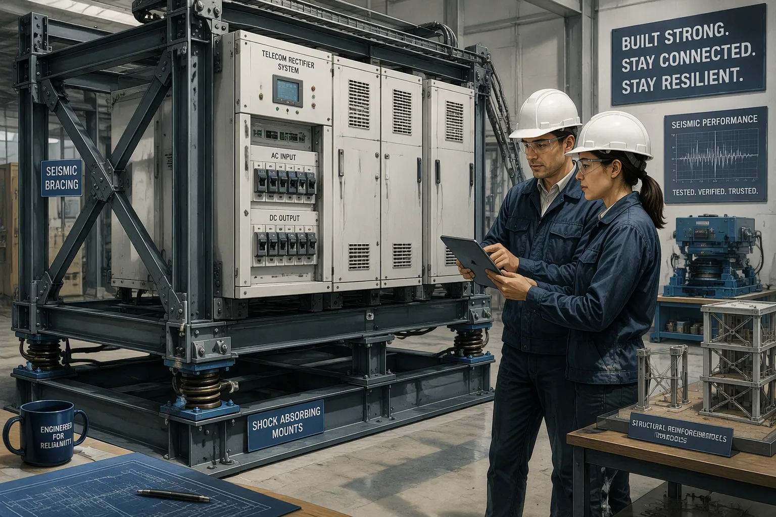
Five strategy layers protect rectifier installations in high-intensity earthquake zones: site-specific hazard analysis, anchorage and enclosure reinforcement, qualification testing, component-level hardening, and lifecycle maintenance. Each layer covers a gap the others leave open, and together they form one continuous defense.
Telecom Rectifier Systems turn incoming AC power into the DC48V that base stations and network equipment need. A failed rectifier silences an entire site, so seismic performance deserves its own engineering review rather than a line in a general procurement checklist.
This post offers practical, standards-aligned guidance. It shows how to select and combine reinforcement options by weighing performance, fit, compliance evidence, and cost.
Key Takeaways
Begin with a site hazard analysis to set the earthquake force your rectifier must survive.
Make the anchor points and enclosures stronger so earthquake forces spread out and the equipment does not tip over.
Use qualification testing and check the full test reports to confirm zone ratings.
Make the parts inside, like batteries and circuit boards, stronger so their connections stay tight.
Plan for regular inspections and checks after earthquakes to keep protection working over time.
Seismic Risk and Site Hazard Analysis
Hazard analysis is the base for every reinforcement choice. It sets the earthquake force that a rectifier setup must survive at a certain site. Engineers then match equipment ratings and structural steps to that force. If you skip this step, later choices — anchorage strength, cabinet rating, test evidence — have no reference point.
Design-Basis Ground Motions
Design-basis ground motions describe the earthquake shaking a telecom site must stand up to. Engineers get them from regional seismic hazard maps, fault studies, and the site's assigned seismic zone. U.S. building codes, like ASCE 7, organize this work around mapped spectral acceleration values and soil site coefficients. The result is a target ground motion level for design.
Zone-based intensity levels turn that target into practical requirements. A high-intensity zone needs stronger anchorage, stiffer cabinets, and more rigorous qualification evidence than a moderate zone. Seismic-rated cabinet zone requirements link straight to equipment selection. A cabinet rated for a lower zone does not belong in a high-hazard site, even when its electrical specs fit perfectly.
Site Conditions and Equipment Location
Local conditions change the ground motion that reaches the equipment. Soft soils boost long-period shaking. Rock sites pass along higher-frequency energy. Building floor response adds another filter: upper floors of tall structures often sway more than the ground, so a rectifier on a top floor may face greater demand than one in a basement.
Equipment placement matters just as much. Installations near structural joints, expansion gaps, or unsupported floor spans feel concentrated movement. Elevation changes the acceleration profile. Designers should place rectifier cabinets close to stiff structural elements and away from areas prone to large drift. Basic earthquake-resistant design concepts — structural symmetry, continuous load paths, and ductile connections — guide these placement choices and frame the reinforcement decisions that follow.
Hazard analysis comes first because every later layer — anchorage, enclosure choice, testing, and component hardening — depends on the demand it defines.
Enclosure and Mounting Reinforcement
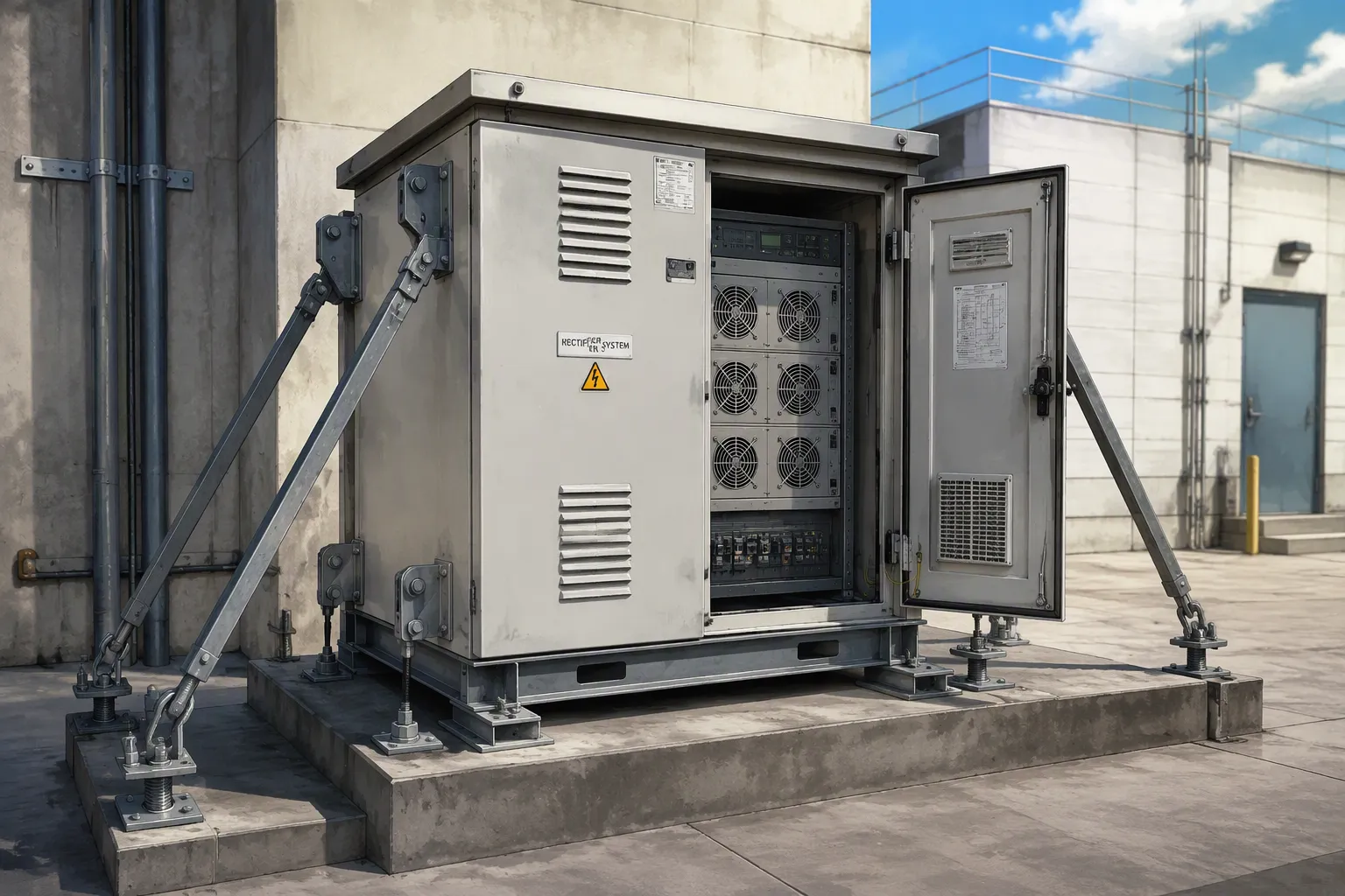
Hazard analysis sets the demand. Enclosure and mounting reinforcement controls how the rectifier setup handles that demand. Good reinforcement spreads seismic forces across the structure and stops damage from building up at weak points.
Anchorage and Bracing Techniques
Anchorage ties the cabinet to the building slab. Post-installed anchors, cast-in-place bolts, and welded base plates all do this job. The choice depends on slab thickness, concrete strength, and the uplift and shear capacity you need. Anchors must resist both tension and shear forces during shaking. Weak anchorage lets the cabinet rock, slide, or tip over.
Lateral bracing adds a second load path. Diagonal braces, rigid frames, and wall ties limit cabinet sway and pass lateral forces to the structure. Connection detailing matters here. Ductile connections bend slowly under extreme loads instead of snapping. This behavior soaks up energy and shields the cabinet from sudden failure.
Drift control keeps floor movement within safe limits. Buildings sway during earthquakes, and too much drift can rip anchored equipment from its base. Designers factor in inter-story drift when they specify anchorage and bracing. Structural symmetry also helps. Symmetric layouts cut torsional forces and keep seismic demand balanced across the installation.
High-strength flexural reinforcement research, such as NIST Task Order 11305, gives background for reinforced concrete equipment housings. This work supports stronger concrete enclosures for critical telecom equipment in high-hazard zones.
Cabinet and Rack Integration
Cabinet-level integration mixes structural strength with environmental protection. ESTEL outdoor telecom cabinets and IP55 base station cabinets with rectifier systems show this approach. The cabinet structure has an earthquake resistance function.
The cabinet structure has an earthquake resistance function.
Several design features support performance in harsh seismic sites:
Feature | Relevance to Seismic Zones |
|---|---|
Anti-corrosion powder coating | Protects the cabinet structure from environmental degradation over time |
Anti-theft locks | Secure equipment and maintain enclosure integrity |
Heat insulation | Stabilizes internal temperatures for reliable rectifier operation |
Earthquake-resistant packaging | Free-fumigation plywood with good cushioning and high strength protects equipment during transport and installation |
Rack integration extends reinforcement inside the cabinet. Rectifier modules mount in standard 19-inch racks with secure fasteners. The rack frame ties into the cabinet structure, so seismic forces travel through a continuous load path from module to rack to cabinet to anchorage. This chain stops any single connection from carrying concentrated stress.
Cabinet selection should match the zone rating from the hazard analysis. A cabinet rated for a lower seismic zone does not belong in a high-hazard site, even when its electrical specs fit. Buyers should confirm that the cabinet's structural rating lines up with the site's design-basis ground motion.
Seismic Qualification and Code Compliance
Standards and Test Methods
Qualification testing shows that a rectifier cabinet or rack can handle the shaking set by the hazard analysis. Shake-table testing is the most direct way to do this. Engineers put the equipment on a powered table and shake it with recorded or made-up ground motions. The test copies real earthquake movement and shows how anchorage, cabinet frames, and internal modules act together.
Analysis-based qualification is another option when physical testing is not practical. Engineers build a structural model of the cabinet and its contents, apply seismic loads, and check stresses and deflections against acceptance limits. This method works well for large or custom installations. Standards tie these methods together. ASCE 7 sets the design loads, ICC-ES AC156 defines a widely used shake-table protocol for nonstructural components, and Telcordia GR-63-CORE covers seismic testing for telecom equipment. Specifiers should confirm which standard a supplier tested against.
Reading Certification Evidence
A test report means more than a certificate alone. Buyers should check the report's scope: which cabinet model, which configuration, and which mounting method the lab actually tested. A rating earned on a bare cabinet may not cover a cabinet loaded with rectifier modules and batteries. The tested mass and center of gravity must match the real installation.
Zone ratings need careful reading. A cabinet rated for a moderate zone does not automatically qualify for a high-hazard site. The report should state the input motion level and the acceptance criteria the unit met. Certification scope also matters. An accredited third-party lab adds credibility over an in-house test. Specifiers should request the full report, check the tested configuration against the planned one, and keep that evidence on file for code review and future retrofits.
Component-Level Reinforcement for Telecom Rectifier Systems
Hardening Batteries and Circuit Boards
Structural reinforcement protects the cabinet shell. Component-level measures protect what sits inside. Battery racks need firm restraint against sliding and tipping. Anchoring lithium iron phosphate batteries to the rack base keeps heavy cells from shifting during strong shaking. Restraint straps and bolted hold-downs add a second layer of control.
Circuit boards need similar attention. Board retention clips and standoffs stop modules from jumping out of their slots. Connector locking mechanisms keep power and signal plugs seated under vibration. These small parts carry large consequences. A loose connector can cut DC output to a live site even when the cabinet itself survives intact.
Internal Connections and Modular Design
Internal connections complete the load path inside the enclosure. ESTEL's Telecom Rectifier System shows how modular construction supports this goal. The system comes in 2U, 3U, and 6U rack-mount designs with DC48V output and AC220V or 380VAC input options. Efficiency exceeds 96 percent. Copper bar grounding gives a solid, low-resistance path for fault and seismic-induced currents, and the flexible cable inlet eases wiring in tight cabinet spaces.
Modularity helps inspection and post-event maintenance. Each rectifier module slides out on its own, so technicians can check mounts, connectors, and boards without dismantling the whole rack. After an earthquake, crews can test and swap individual modules fast. That speed shortens downtime and protects power continuity for the site. Buyers should confirm that module fasteners and rack interfaces meet the same seismic rating as the cabinet.
Comparing Reinforcement Options
Performance, Fit, and Compliance
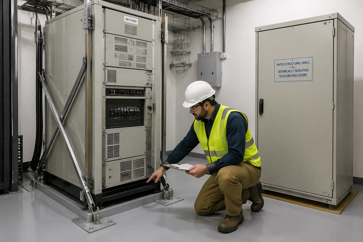
There are four ways to reinforce a rectifier setup: anchorage upgrades, enclosure replacement, rack-level bracing, and component hardening. Each one fixes a different problem, and each one works best at a different site.
Option | Technical Performance | Application Fit | Compliance Role |
|---|---|---|---|
Anchorage upgrades | Increases uplift and shear strength at the base | Good for retrofits where the cabinet is solid but the base is weak | Backs up the load path assumed in the design-basis analysis |
Provides a rated structural shell and full environmental protection | Best for new builds or cabinets past their service life | Brings a documented zone rating to the site | |
Rack-level bracing | Limits sway and protects internal modules | Works for dense racks with heavy rectifier and battery loads | Adds to cabinet qualification but does not replace it |
Component hardening | Keeps batteries, boards, and connectors in place | Fits any site as a low-disruption add-on | Handles internal failure modes that tests may not cover |
Anchorage upgrades give the best return when the cabinet already meets its zone rating. Enclosure replacement makes sense when the existing shell lacks certification or shows corrosion damage. Rack-level bracing fits sites with tall, top-heavy racks. Component hardening works everywhere, and crews can add it during routine maintenance windows.
Compliance evidence sets these options apart. A new enclosure usually comes with a test report. Anchorage upgrades and bracing often need engineering calculations signed by a structural engineer. Specifiers should confirm that the whole system, not just one part, meets the site's design-basis ground motion.
Cost and Lifecycle Tradeoffs
Upfront price tells only part of the story. Each option has its own maintenance needs, service life, and repair burden. Anchorage upgrades cost little in materials but need engineering review and installation labor. Enclosure replacement has the largest initial cost and gives the longest service life with the least follow-up work. Rack-level bracing falls in the middle. Component hardening costs the least per unit and needs periodic re-checks after every event.
The rebar industry offers a useful parallel. Galvanized reinforcement costs more upfront than conventional black rebar, yet owners often recover the investment through reduced maintenance, fewer repairs, longer service life, and lower lifecycle costs. Structures built for several decades of service — bridges, parking structures, coastal developments, marine infrastructure, and water treatment facilities — often justify that premium. In low-corrosion settings such as interior buildings and dry foundations, the extra spend may not deliver enough long-term value. Environmental exposure, design life, maintenance expectations, and budget should guide the choice.
Telecom Rectifier Systems follow the same logic. A high-hazard site with decades of planned service rewards deeper reinforcement, because downtime costs dwarf the material premium. A moderate-hazard site with a short remaining lease may only need bracing and component hardening. Owners should weigh total cost of ownership across the full service life, not the invoice alone.
Implementation and Maintenance
Installation and Retrofit Workflow
A retrofit follows a set order. First, a structural engineer looks over the hazard analysis and confirms anchor capacity, brace locations, and drift limits. Next, crews check the existing cabinet base and slab condition. They then install anchorage and bracing, torque fasteners to the engineer's specification, and write down each connection. Finally, they reconnect and test the rectifier load.
Power continuity drives the schedule. Crews stage the cutover so live sites never lose DC output. They move rectifier modules to a temporary rack, reinforce the primary position, then return the modules. Battery strings stay online the whole time. This staged approach keeps Telecom Rectifier Systems feeding the network while structural work goes on around them.
Inspection and Post-Event Verification
Anchorage and bracing need regular inspection. Crews check anchor torque, look for cracked welds, and confirm that braces stay straight and tight. Corrosion on base plates deserves attention at every visit. Inspectors record findings in a maintenance log that ties each connection to its original design calculation. That record supports code review and guides the next retrofit.
After an earthquake, a verification walk-through comes before any restart. Technicians inspect anchors for elongation, check cabinet plumb, and test module seating and connector locks. They photograph damage and compare it against the baseline documentation. Only then does the site return to normal operation. This discipline protects both the equipment and the people who service it.
Keeping rectifier setups safe in earthquakes follows a clear order. Hazard analysis comes first and sets the demand. Next comes anchorage and enclosure reinforcement, then qualification testing, component hardening, and ongoing maintenance. Each layer covers a gap the others leave open.
Decision-makers should match how much reinforcement they add to the site's hazard level and importance. They should check compliance evidence against the planned setup, not just the certificate. Lifecycle cost should count more than upfront price, because downtime at a critical site costs more than any material premium.
Telecom Rectifier Systems serve live networks for many years. Treat seismic resilience as an ongoing program, not a one-time purchase. Regular inspection and post-event checks keep continuous power flowing to the infrastructure that depends on it.
FAQ
How does a site's seismic zone affect rectifier cabinet selection?
The zone sets the design-basis ground motion from the hazard analysis. Specifiers then pick a cabinet whose tested zone rating meets or beats that demand. A cabinet rated for a lower zone does not qualify for a high-hazard site, even when its electrical specs fit.
Can crews reinforce an existing rectifier installation without replacing the cabinet?
Yes. Anchorage upgrades, rack-level bracing, and component hardening all work as retrofits. Crews stage the cutover so live sites keep DC output. Enclosure replacement becomes the better choice when the existing shell lacks certification or shows corrosion damage.
What evidence should a buyer request from a rectifier supplier?
Buyers should ask for the full test report, not just a certificate. The report should name the tested cabinet model, configuration, mounting method, and input motion level. An accredited third-party lab adds credibility. ASCE 7, ICC-ES AC156, and Telcordia GR-63-CORE frame the common test landscape.
How often should teams inspect anchorage and bracing?
Inspection belongs in the routine maintenance cycle. Crews check anchor torque, welds, brace alignment, and base-plate corrosion at each visit. A post-earthquake walk-through comes before any restart. Inspectors log findings against the original design calculation to support code review.
Does component hardening replace structural reinforcement?
No. Component hardening handles internal failure modes that cabinet tests may not cover, such as battery shift or loose connectors. It complements anchorage and enclosure work. The layered strategy still starts with hazard analysis and ends with sustained maintenance.
See Also
Ensuring Consistent Power Delivery For Telecom Cabinet Operations
Structural Design Guidelines For ESTEL Telecommunication Cabinet Systems
Grid-Tied Solar Inverter And Battery System For Telecom Cabinets
Solar Energy Storage Power System For Telecom Cabinet Applications
Essential Structural Design Points For ESTEL Integrated Outdoor Telecom Cabinets
CALL US DIRECTLY
86-13752765943
3A-8, SHUIWAN 1979 SQUARE (PHASE II), NO.111, TAIZI ROAD,SHUIWAN COMMUNITY, ZHAOSHANG STREET, NANSHAN DISTRICT, SHENZHEN, GUANGDONG, CHINA
