How to Size a 48V Telecom Rectifier System for Your Site's Power Requirements
Accurate sizing of a 48V rectifier system ensures your telecom cabinet receives a reliable power supply, especially as 5g networks demand more from every component. If you underestimate the supply needed, you risk downtime and reduced efficiency. When you consider all equipment loads, redundancy, and future growth, you create a foundation for long-term success. Environmental factors such as temperature or altitude can also impact supply performance. ESTEL’s Telecom Rectifier System offers a high-efficiency solution, with modern designs reaching over 96% efficiency. The table below shows how proper system sizing has improved supply efficiency across the telecom industry, which is especially important for 5g deployments.
Model | Efficiency Improvement |
|---|---|
Older Models (Pre-2008) | ~92% |
Flatpack2 HE (2008) | 96.5% |
Flatpack2 SHE (Newer) | 98% |
You need a system that not only meets today’s 5g supply demands but also supports the reliability and scalability of your telecom cabinet.
Identify Telecom Cabinet Power Loads
List All Equipment
You need to start by listing every device inside your telecom cabinet. This step forms the foundation for accurate sizing of your 48 vdc power system. The telecom cabinet often contains a variety of equipment that draws dc power. Common examples include:
Equipment Type | Description |
|---|---|
DC Power Systems | Systems that supply dc power to telecom equipment. |
Telecom Batteries | Batteries that store and deliver dc power. |
DC Enclosures | Cabinets designed for dc infrastructure and connections. |
You may also find network switches, routers, and monitoring devices that require dc input. Make sure you include all telecom equipment, even smaller devices like monitoring sensors or network interface modules. Missing any device can lead to underestimating your total power load requirements, which impacts the reliability of your telecom cabinet.
Tip: Walk through your telecom cabinet with a checklist and physically verify each piece of equipment. This hands-on approach helps you avoid missing hidden or less obvious devices.
Gather Power Ratings
After you list all equipment, you must gather the power ratings for each device. Look for labels on the equipment, check the user manuals, or consult the manufacturer’s datasheets. Record the dc voltage, current (amps), and power (watts) for each item. For a telecom dc power system, focus on the 48 vdc power ratings, as this is the standard for most telecom cabinets.
Effective documentation is essential. Create a table or spreadsheet to record key metrics such as voltage, current, and power for each device. This practice supports ongoing monitoring and makes troubleshooting easier if your network experiences issues. Monitoring these values also helps you plan for future upgrades and ensures your power system can handle increased loads.
Selecting the right power system for your telecom cabinet depends on the accuracy of your equipment list and power ratings. Proper monitoring and documentation ensure your 48 vdc power solution meets your network’s current and future needs, supporting both reliability and scalability.
Calculate Total System Power Requirement
Sizing your 48V rectifier system starts with a clear understanding of your total power needs. You must know exactly how much power your telecom cabinet will draw under normal and peak conditions. This step ensures your dc power system delivers reliable performance and supports every device in your setup.
Sum Power Consumption
Begin by adding up the power ratings for every device you listed in your telecom cabinet. Each piece of equipment, from major dc power systems to small monitoring modules, contributes to the total power demand. You should check the labels or datasheets for each device to find the dc power rating, usually given in watts. If a device lists only voltage and current, you can calculate the power using the formula:
Power (W) = Voltage (V) × Current (A)
Create a table or spreadsheet to organize this information. List each device, its dc voltage, current, and power rating. This method helps you avoid missing any equipment and ensures you capture the full power profile of your telecom cabinet.
Device Name | DC Voltage (V) | Current (A) | Power (W) |
|---|---|---|---|
DC Power System | 48 | 10 | 480 |
Telecom Battery | 48 | 5 | 240 |
Network Switch | 48 | 2 | 96 |
Monitoring Module | 48 | 1 | 48 |
Add the power values for all devices. The sum gives you the total power requirement in watts for your telecom cabinet. This total forms the basis for sizing your rectifier system. Missing even a small device can lead to underestimating your power needs, which can cause system failures or reduced efficiency.
Tip: Always include every device, even those with low power ratings. Overlooking small dc loads can add up and affect the overall power calculation.
Convert Watts to Amps at 48V
Once you have the total power in watts, you need to convert this value to amps at 48V. Rectifier systems are rated by their output current, so this step is essential for selecting the right model. Use the following formula to make the conversion:
Current (A) = Power (W) / Voltage (V)
For example, if your total power requirement is 864 watts and your system operates at 48V dc, the calculation looks like this:
Current (A) = 864 W / 48 V = 18 A
This means your rectifier system must supply at least 18 amps of dc current at 48V to meet your telecom cabinet’s power needs. Always round up to the next whole number to provide a safety margin.
You should also remember that the total current must cover all connected devices. If you plan to add more equipment in the future, consider this in your calculation. Properly sizing your rectifier system ensures your telecom cabinet remains reliable, efficient, and scalable. The power system acts as the backbone of your telecom solution, supporting every device and maintaining stable voltage across all loads.
Note: Accurate power calculations protect your telecom infrastructure from overloads and downtime. A well-sized dc power system keeps your network running smoothly, even as your requirements grow.
A carefully calculated power system not only meets your current needs but also supports future expansion. By following these steps, you ensure your telecom cabinet operates at peak efficiency and reliability, with the right dc voltage and current for every device.
Ensure Redundancy and Reliable Power Supply
N+1 and N+2 Redundancy
You must prioritize redundancy when designing your dc power system for telecom applications. Redundancy ensures that your site maintains maximum uptime, even if one rectifier fails. Two common redundancy configurations are N+1 and N+2.
N+1 redundancy uses N rectifiers to meet the full dc load, with one extra rectifier as a backup. If one rectifier fails, the backup takes over, so your power supply remains stable.
N+2 redundancy involves two independent systems, each with N+1 rectifiers. Each system includes a backup, which provides even greater reliability and resilience for your dc power supply.
You can calculate the number of rectifiers needed by first determining the total dc load. Divide the total dc current requirement by the rated output of one rectifier. Add one more rectifier for N+1 redundancy, or design two parallel systems for N+2. This approach ensures your telecom cabinet always has a backup power source ready to maintain continuous connectivity.
ESTEL’s Telecom Rectifier System supports modular redundancy. You can add or replace rectifiers without shutting down the dc power system. This modular design allows you to scale your power backup systems as your site grows, while always maintaining high reliability.
Importance for Telecom Sites
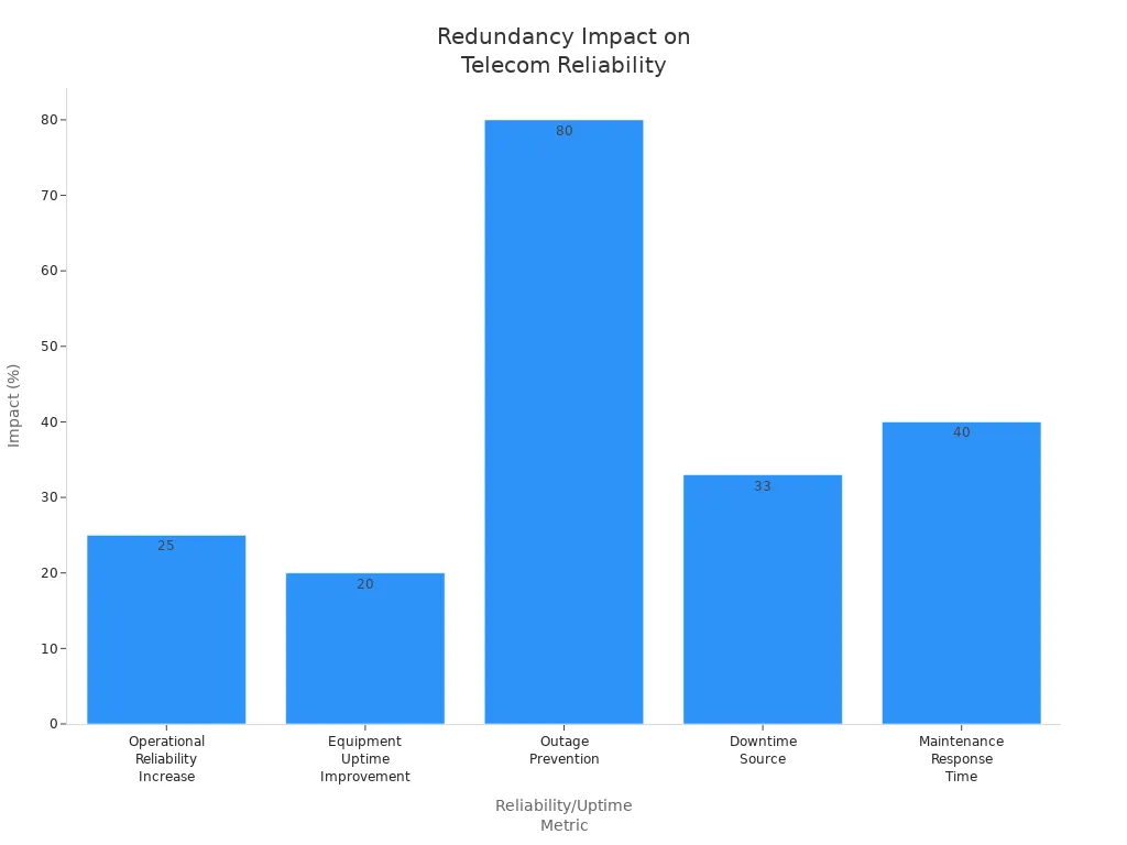
Redundancy plays a vital role in telecom site reliability. A robust dc power system with backup rectifiers and battery support protects your equipment from outages. The table below shows how redundancy improves operational reliability and uptime for telecom sites:
Evidence Type | Statistic/Impact |
|---|---|
Operational Reliability Increase | 25% increase in operational reliability |
Equipment Uptime Improvement | 20% improvement in equipment uptime |
Outage Prevention | Proactive monitoring prevents up to 80% of outages |
Downtime Source | 33% of downtime stems from power outages |
Maintenance Response Time | 40% faster maintenance response times |
Predictive Analytics | Anticipates failures weeks in advance |
A well-designed dc power system with redundancy ensures stable ac power output and reliable battery backup. You reduce the risk of downtime and protect your telecom equipment. Modular rectifiers also improve reliability and make maintenance easier.
Modular rectifier systems allow you to add power modules as your dc load grows. This flexibility prevents overprovisioning and keeps costs aligned with actual needs. If one module fails, others continue to supply power, so your telecom site stays online. Traditional systems often require costly shutdowns for upgrades, but modular designs keep your network running.
You must treat your dc power system as the backbone of your telecom cabinet. Proper sizing and redundancy planning guarantee power reliability, efficient supply, and long-term scalability.
Plan for Expansion and Environmental Factors

Allow Margin for Growth
You should always plan for future expansion when sizing your dc power system. Telecom sites often add new equipment or upgrade existing devices. If you size your rectifier system only for current loads, you risk running out of capacity as your needs grow. Add extra dc power capacity to support new modules, batteries, or network upgrades. This margin helps you avoid costly downtime and ensures your telecom cabinet remains reliable. Many experts recommend increasing your calculated dc power requirement by 20–30% to allow for growth. This approach keeps your system scalable and ready for new technology.
Tip: Review your site’s upgrade plans and estimate the additional dc power needed for future equipment. This step protects your investment and supports long-term telecom reliability.
Adjust for Temperature and Altitude
Environmental factors such as temperature and altitude can affect your dc power system’s performance. High temperatures reduce the maximum output of rectifier modules. At higher altitudes, the maximum operating temperature drops, which impacts power delivery. You must derate your rectifier system to maintain reliability and efficiency. The table below shows how temperature and altitude influence dc power output:
Parameter | Description |
|---|---|
Ambient Temperature | Normal full load operation between -10°C and 45°C; derating required from 45°C to 65°C |
Altitude Effect | Maximum operating temperature decreases by 1°C for every 200m above 3000m altitude |
Derating Behavior | Power output reduced at higher ambient temperatures to prevent overheating and ensure reliability |
Humidity and dust also impact your dc power system. High humidity can cause short circuits and corrosion. Dust buildup leads to overheating and reduces efficiency. You should use dehumidifiers and protective coatings to safeguard your rectifier modules. These steps help maintain stable dc power and extend the life of your telecom cabinet.
Consider Rectifier Efficiency
Rectifier efficiency plays a key role in your telecom cabinet’s performance. High efficiency means less energy loss and lower operational costs. Modern dc power systems reach up to 97–98% efficiency, which greatly improves power conversion efficiency. The table below highlights the benefits of advanced rectifier systems:
Metric | Value |
|---|---|
Efficiency Rating | Up to 97-98% |
Power Loss Reduction | Up to 75% compared to older rectifiers |
Power Factor Correction | 0.95-0.99 |
High efficiency minimizes energy loss, which lowers your energy bills.
Lower heat output reduces cooling needs and emissions.
Advanced rectifier technology supports renewable energy integration and boosts sustainability.
ESTEL’s Telecom Rectifier System delivers over 96% efficiency. This high power conversion efficiency ensures your dc power system supports every device in your telecom cabinet. You gain reliable power, reduced costs, and a scalable solution for future growth.
Remember: Proper sizing and selection of your dc power system directly impact the reliability, efficiency, and scalability of your telecom cabinet. Always consider expansion, environmental factors, and rectifier efficiency to build a robust telecom solution.
Select the Right ESTEL Telecom Rectifier System
Match System to Site Needs
You need to match the ESTEL Telecom Rectifier System to your site’s unique needs. Start by reviewing the total current and power you calculated earlier. The system you choose must handle both your steady and peak loads without risk of failure. ESTEL offers a range of models with different output currents, so you can select the system that fits your cabinet’s demands.
When you compare options, focus on these key factors:
Input and output voltage ratings. The system must match your power source and deliver a stable 48V output for all telecom equipment.
Current and load requirements. The system should support your maximum load, including any future expansion.
Ripple voltage and filtering. Low ripple voltage protects sensitive devices. ESTEL systems use advanced filters to keep your equipment safe.
Safety features. Look for overcurrent and overvoltage protection. These features prevent damage during power surges or faults.
Cost and quality balance. Consider the long-term value of the system, not just the initial price. High-quality systems reduce downtime and maintenance costs.
You should also check the physical compatibility of the system with your telecom cabinet. ESTEL’s modular rack-mount designs fit standard 19-inch racks, making installation straightforward. The flexible cable inlet and grounding protection simplify integration with your existing setup.
Tip: Always confirm that the system’s input voltage options (such as 220VAC or 380VAC) match your site’s available power supply. This step prevents installation issues and ensures reliable operation.
A well-matched system forms the backbone of your telecom cabinet. It supports every device, maintains stable voltage, and adapts as your requirements change. When you choose the right system, you protect your investment and ensure your network stays online.
Verify Compliance with Standards
You must verify that your chosen system meets all relevant industry and local standards. Compliance ensures safe and reliable operation for your telecom site. ESTEL designs its systems to meet international standards, including IEC, UL, and IEEE. These certifications show that the system has passed rigorous safety and performance tests.
Check the product documentation for compliance marks before installation. If your site operates in a region with specific local requirements, confirm that the system meets those as well. This step protects your equipment and helps you avoid regulatory issues.
IEC standards cover safety and performance for electrical systems.
UL certification confirms the system meets strict safety guidelines.
IEEE standards ensure reliable operation in telecom environments.
Note: A compliant system reduces the risk of accidents, equipment failure, and downtime. It also makes future upgrades and inspections easier.
Selecting the right ESTEL Telecom Rectifier System is a critical step in building a reliable, efficient, and scalable telecom cabinet. When you match the system to your site’s needs and verify compliance, you lay the foundation for long-term success.
You improve your telecom cabinet’s reliability when you size your 48V rectifier system with accuracy, plan for redundancy, and allow for future growth. Avoid common mistakes such as ignoring load variations, overlooking environmental conditions, neglecting compliance, choosing incompatible packages, and skipping regular testing.
Benefit | Description |
|---|---|
High Efficiency | You reduce energy waste and operational costs with efficiency up to 96%. |
Reliability | You protect your telecom system from outages and power fluctuations. |
Durability | You gain robust construction for harsh environments. |
You can consult with ESTEL or industry experts for complex projects. Expert guidance helps you manage energy, analyze data, and automate preventive maintenance for your telecom power system.
See Also
Methods For Calculating Power Systems And Batteries In Telecom
Battery And Inverter Systems For Telecom Cabinets Using Solar Power
Ensuring A Consistent Power Supply For Telecom Cabinets
Finding The Perfect Size For Your Telecom Cabinet
Energy Storage Solutions Using Photovoltaics For Telecom Cabinets
CALL US DIRECTLY
86-13752765943
3A-8, SHUIWAN 1979 SQUARE (PHASE II), NO.111, TAIZI ROAD,SHUIWAN COMMUNITY, ZHAOSHANG STREET, NANSHAN DISTRICT, SHENZHEN, GUANGDONG, CHINA