Sizing a 48V telecom power system for redundancy

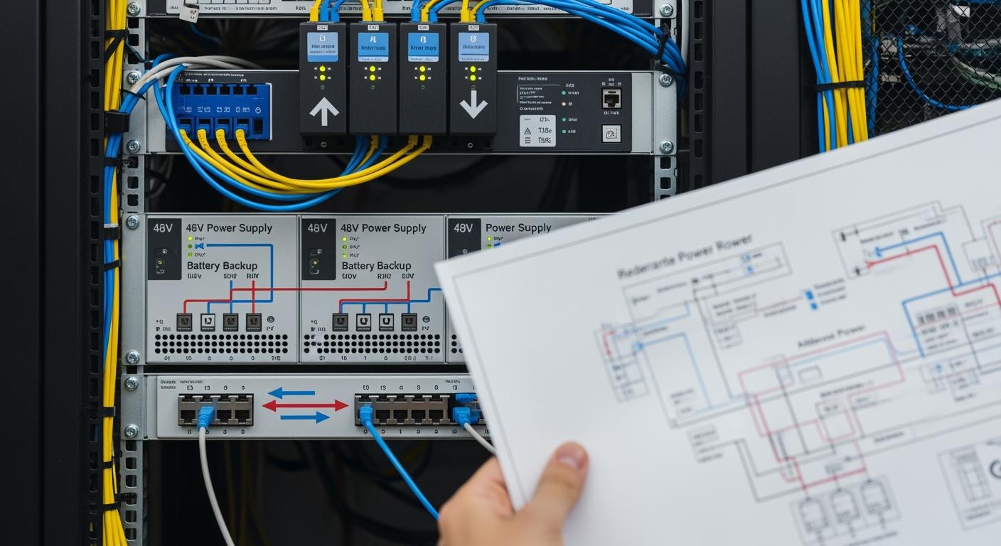
You face critical decisions when sizing a 48V telecom power system. If you underestimate your power needs, network downtime can disrupt communication and damage your reputation.
Inadequate charging infrastructure may leave batteries undercharged and reduce system reliability.
Industry trends show that modular and energy-efficient designs boost uptime and allow you to scale quickly.
Assessing your power requirements helps you match the system to your active devices.
Selecting high-quality equipment ensures optimal performance and safety.
Key Takeaways
Assess your total power load carefully to avoid network downtime and ensure reliability.
Choose high-quality equipment and implement N+1 redundancy to maintain continuous service.
Plan for future growth by considering potential increases in power demand and technology changes.
Utilize remote monitoring tools to catch issues early and maintain system uptime.
Conduct regular load testing and preventive maintenance to extend the lifespan of your telecom power system.
Assessing 48V Telecom Power System Loads

Identifying Total and Critical Loads
You need to start by listing every device that relies on your 48V telecom power system. Focus on equipment such as routers, switches, base stations, and monitoring devices.
Tip: Always check the power specifications for each device before you add them to your list.
To accurately assess your total and critical loads, follow these steps:
Identify all critical devices and record their power ratings.
Calculate the total power requirements for your -48V DC system.
Check that your UPS, generators, and power distribution units can support the calculated load.
Plan for redundancy using models like N+1 or 2N.
Monitor environmental factors, including temperature and altitude, which can affect capacity.
Choose energy-efficient components to lower operational costs.
Perform load testing to confirm system capacity.
Use real-time monitoring tools for ongoing management.
Prepare for emergency and failover scenarios.
Follow industry standards and regulations.
Estimating Peak and Average Demand
You must estimate both peak and average demand to avoid overloads and ensure stable operation. Review historical data from your monitoring systems. Look for periods when demand spikes, such as during network upgrades or maintenance.
Note: Peak demand often occurs during emergencies or unexpected events.
Calculate the average demand by tracking daily usage patterns. Use this information to size your 48V telecom power system so it can handle both typical and extreme conditions. This approach helps you maintain uptime and protect critical services.
Planning for Future Growth
You should plan for future expansion when sizing your 48V telecom power system. Technology changes quickly, and your network may need more capacity soon. Use proactive resistance testing to check battery health and predict performance. Onboard SOH (State of Health) and SOC (State of Charge) analysis gives you real-time data on battery status. Remote monitoring lets you manage your system from anywhere.
Technology Type | Features |
|---|---|
Proactive Resistance Testing | Checks each cell’s health and predicts performance. |
Onboard SOH and SOC Analysis | Provides real-time data on battery health and charge state. |
Remote Monitoring Capabilities | Lets you monitor your system from anywhere, improving operational efficiency. |
You can optimize performance by assembling cells carefully, installing protection devices, and using battery cooling systems. Schedule regular safety tests and maintenance to keep your system reliable. Monthly visual inspections help you spot corrosion, leaks, or swelling early. Adjust inspection frequency based on battery usage and performance trends.
Calculating Power and Backup Needs
Determining Total Power Demand
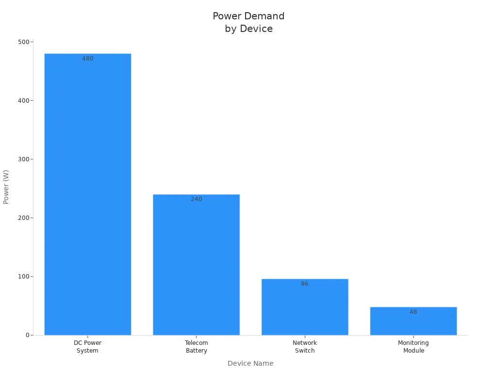
You must start by calculating the total power demand for your site. List each device that connects to your 48V telecom power system. Record the voltage and current for every device. Add up the power requirements to get the total load.
Here is a sample table to help you organize your data:
Device Name | DC Voltage (V) | Current (A) | Power (W) |
|---|---|---|---|
DC Power System | 48 | 10 | 480 |
Telecom Battery | 48 | 5 | 240 |
Network Switch | 48 | 2 | 96 |
Monitoring Module | 48 | 1 | 48 |
You can convert total power in watts to amps using the formula:
Current (A) = Power (W) / Voltage (V).
For example, if your total power requirement is 864 watts, divide by 48 volts. You need 18 amps from your rectifier system.
Sizing Battery Backup for Uptime
You must size your battery backup to keep your network running during outages. Use these formulas:
Battery Capacity (Ah) = Load (W) × Backup Time (h) ÷ Battery Voltage (V)
Backup Time (h) = Battery Capacity (Wh) / Total Load (W)
Choose batteries that match your calculated capacity. ESTEL's Telecom Power System supports flexible battery configurations and wide input voltage. Natural cooling reduces maintenance and improves reliability.
Tip: Always plan for longer backup times than you think you need. This protects your network during unexpected events.
Factoring in Peak Loads
You must consider peak loads when sizing your system. Review historical data to find times when demand spikes. Size your rectifier and battery system to handle these peaks. ESTEL's Telecom Power System adapts to changing loads and offers multiple communication ports for monitoring. This helps you maintain uptime and avoid overloads.
Selecting Equipment with ESTEL Solutions
Choosing Rectifiers for Redundancy
You need to select rectifiers that match your system’s voltage and current requirements. ESTEL’s Telecom Rectifier System delivers consistent DC48V output and supports parallel operation. You can connect multiple rectifiers to share the load and improve reliability. N+1 redundancy ensures your network stays online if one rectifier fails. Hot-swap capability lets you replace modules without shutting down the system. This feature keeps your operations running and simplifies maintenance.
Criteria | Description |
|---|---|
Voltage and Current Ratings | Match the rectifier module's voltage and current ratings to system specifications. |
Redundancy Types | Implement N+1 redundancy for backup capacity; consider cold-standby and hot-standby options. |
Parallel Operation | Connect multiple rectifiers in parallel to share load and enhance reliability. |
Reliability Benefits | Redundant systems improve uptime and simplify maintenance, reducing the risk of downtime. |
Tip: Modular rack-mount designs make upgrades and repairs easier. You can scale your system as your network grows.
Sizing Batteries and Distribution Units
You must size batteries and distribution units based on accurate load assessment. ESTEL’s Telecom Power System uses maintenance-free batteries that support continuous operation. You should consider peak load demands to avoid outages during brief surges. Calculate the autonomy period by reviewing local grid reliability and expected outage durations. Temperature extremes affect battery performance, so proper thermal management is essential. Depth of Discharge impacts battery cycle life. Limiting DoD extends operational life. Battery aging and degradation must be factored into initial sizing. Choose battery chemistry that fits your energy density and cycle life needs. Voltage matching between battery banks and inverters prevents system failure. Adequate charging infrastructure ensures batteries recharge effectively.
Accurate load assessment prevents system performance issues.
Peak load demands require careful planning.
Autonomy period depends on local grid reliability.
Temperature extremes demand proper thermal management.
Depth of Discharge affects battery cycle life.
Battery aging and degradation influence backup power sizing.
Battery chemistry impacts reliability and energy density.
Voltage matching is critical for safe operation.
Charging infrastructure must support effective battery recharge.
Note: ESTEL’s modular PDUs grow with your needs. Hot-swappable parts allow maintenance without shutting down the system.
Integrating ESTEL Telecom Power and Rectifier Systems
You can integrate ESTEL Telecom Power and Rectifier Systems to maximize reliability. Modular configuration allows easy installation and seamless integration with existing setups. Real-time monitoring provides ongoing oversight of system performance. Advanced cooling systems help maintain optimal operating conditions and enhance system longevity. Integrated sensors offer real-time control and alerts for quick issue resolution. Dual power inputs provide N+1 redundancy. Automatic transfer switches enable seamless switching between power sources. Remote monitoring lets you respond quickly to potential issues.
Feature | Description |
|---|---|
Modular Configuration | Allows for easy installation and integration with existing setups. |
Real-time Monitoring | Provides ongoing oversight of system performance to ensure reliability. |
Advanced Cooling Systems | Helps maintain optimal operating conditions, enhancing system longevity. |
Callout: ESTEL’s modular and rack-mount designs support redundancy and easy maintenance. You can scale your 48V telecom power system as your network expands.
Feature | Benefit |
|---|---|
Modular Configuration | Offers scalability, easy upgrades, and redundancy for telecom sites. |
Hot-Swap Capability | Allows replacement of modules without system shutdown, ensuring uptime. |
Integrated Monitoring Systems | Provides real-time data on system performance, improving uptime. |
Maintenance-Free Batteries | Ensures continuous operations without regular upkeep. |
Wide Input Voltage Range | Supports deployment in various environments without local grid concerns. |
Advanced Safety Features | Protects against overvoltage and short circuits for safe operation. |
You gain flexibility and reliability when you choose ESTEL solutions. You can maintain uptime, simplify maintenance, and protect your network from unexpected failures.
Designing for Reliability
System Layout and Space Planning
You improve reliability when you plan your system layout carefully. Start with a thorough site survey. Assess pathways, risers, room layouts, and available rack space. Early coordination between outside plant (OSP) and inside plant (ISP) prevents conflicts at entry points and ensures smooth fiber transitions. Focus on power and grounding needs. Proper planning for electrical requirements and HVAC keeps your system running and compliant. Plan for scalability by reserving extra riser space and using modular racks. You can expand easily as your network grows. Label and document every asset. Clear labeling simplifies troubleshooting and maintenance.
Best Practice | Description |
|---|---|
Assess pathways, risers, room layouts, and rack space. | |
Align OSP and ISP Early | Coordinate entry points for seamless fiber transitions. |
Plan electrical needs, grounding, and HVAC for uptime and compliance. | |
Plan for Scalability | Reserve space and use modular racks for future expansion. |
Label and Document Everything | Simplify maintenance and audits with clear labeling and documentation. |
Cable Routing and Grounding
You protect your telecom power system by following best practices for cable routing and grounding. Consistent grounding and bonding minimize electrical faults and enhance system security. Use low-impedance grounding systems. Aim for a resistance of 5 ohms or lower to dissipate energy during surges. Apply bonding techniques like Star-IBN and Mesh-IBN. These methods interconnect grounding points, reduce potential differences, and improve safety.
Consistent grounding and bonding practices enhance security and reliability.
Low-impedance grounding systems dissipate energy effectively during surges.
Bonding techniques like Star-IBN and Mesh-IBN interconnect grounding points and reduce risks.
Tip: Proper cable routing prevents interference and makes maintenance easier.
Safety and Compliance
You must meet safety and compliance standards to protect your equipment and personnel. NEMA ratings classify enclosures based on environmental protection. NEMA 1 suits indoor use and basic dust protection. NEMA 3R protects against rain and snow for outdoor sites. NEMA 4X offers enhanced corrosion protection in harsh environments. IP ratings measure protection against solids and liquids. IP54 limits dust ingress and water splashes. IP65 is dust-tight and resists water jets. IP67 withstands temporary immersion. Regulatory compliance ensures your system meets operational standards, minimizes risks, and boosts reliability.
NEMA ratings define enclosure protection for different environments.
IP ratings measure resistance to dust and water.
Regulatory compliance maintains safety and operational standards.
Note: You improve reliability and safety when you follow these guidelines during system design.
Redundancy Strategies for 48V Telecom Power Systems

Building redundancy into your 48V telecom power system helps you avoid downtime and maintain continuous service. You can use several strategies to ensure your network stays online, even if a component fails.
N+1 and N+2 Configurations
You can choose between N+1 and N+2 redundancy to match your reliability needs. N+1 means you add one extra module beyond what you need for normal operation. N+2 means you add two extra modules. The table below shows the differences:
Configuration | Description | Benefits | Limitations |
|---|---|---|---|
N+1 | Includes one extra module beyond the required number to ensure operation if one fails. | Cost-effective, maintains continuous power supply. | Limited to one module failure without impact. |
N+2 | Includes two extra modules, allowing for the failure of two modules without performance impact. | Higher reliability, suitable for critical environments. | Increased initial investment. |
ESTEL’s modular rectifier systems make it easy for you to implement these configurations. You can scale your system as your network grows. Maintenance-free batteries and load low voltage disconnects also help you extend uptime and reduce the risk of failure.
Component | Contribution to System Reliability and Uptime |
|---|---|
Modular Rectifier Systems | Enable continuous operation through redundancy; allow scalability and upgrades; minimize service interruptions. |
Maintenance-Free Batteries | Extend asset life and reduce replacements, supporting continuous operation. |
Load Low Voltage Disconnects | Preserve battery capacity during disturbances, further extending uptime. |
Fault Isolation and Hot-Swap Features
You can improve reliability by using fault isolation and hot-swap features. Fault detection monitors for overcurrent, short circuits, or overheating. If a problem occurs, the system safely disconnects the faulty module. Power sequencing ensures modules turn on and off in the correct order. Load disconnect and bleed functions allow you to remove modules safely. Digital status and alerts give you instant feedback about faults or module status.
Technique | Description |
|---|---|
Fault Detection | Monitors for overcurrent, short circuit, thermal runaway, and safely disconnects if a fault is detected. |
Power Sequencing | Ensures power is applied and removed in the correct order for multi-rail systems to avoid latch-up or misoperation. |
Load Disconnect & Bleed | Provides fast isolation and safe discharge during module removal. |
Status & Alerts | Digital interfaces provide immediate feedback on card presence, faults, or operating status. |
Hot-swap capability lets you replace modules without shutting down your system. You keep your network running while performing maintenance or upgrades.
Dual Power Feeds and Transfer Switching
You can use dual power feeds to supply your system from two independent sources. If one source fails, the other takes over instantly. This seamless transition protects your critical equipment and keeps your network online. You achieve 2N redundancy by duplicating key components, including power supplies and distribution units. This approach helps you handle failures without affecting operations.
Dual input PDUs ensure continuous power by switching between sources automatically.
Seamless transfer switching prevents downtime and protects your equipment.
2N redundancy allows your infrastructure to withstand multiple failures.
Tip: Redundancy strategies like these help you maintain uptime and deliver reliable service, even in demanding environments.
Testing, Monitoring, and Maintenance
Load Testing and Validation
You ensure your 48V telecom power system performs reliably by conducting regular load testing and validation. Start by using 48V DC load banks to simulate real electrical loads. This process helps you verify that your power sources can handle the demands of your network. Schedule testing during off-peak hours to avoid disrupting normal operations. Select a load bank that matches your specific requirements. Maintain and calibrate your load bank regularly to guarantee accurate results. Train your staff on proper load bank usage to minimize errors. You may also consider professional services for testing if you want enhanced efficiency and accuracy.
Use 48V DC load banks to simulate electrical loads.
Plan testing during off-peak hours.
Select a load bank that fits your needs.
Perform maintenance and calibration checks.
Train employees on load bank operation.
Consider outsourcing testing to experts.
Tip: Routine load testing helps you identify weaknesses before they cause downtime.
Remote Monitoring and Alarms
You monitor your telecom power system remotely to catch issues early and maintain uptime. LiteVu™ Optical Monitoring gives you non-intrusive access to critical system information. Sensaphone tracks power loads, temperature, humidity, and security status. Intelligent Power Distribution Units (PDUs) monitor voltage and current, helping you detect anomalies before they become problems.
LiteVu™ Optical Monitoring provides real-time system data.
Sensaphone monitors environmental and security conditions.
Intelligent PDUs track voltage and current for early warning.
Callout: Remote monitoring lets you respond quickly to alarms and prevent outages.
Preventive Maintenance and Audits
You protect your telecom power system by performing preventive maintenance and audits. Most companies schedule maintenance monthly or quarterly. The frequency depends on equipment usage, criticality, and vendor recommendations. Regular maintenance keeps your system running smoothly and extends its lifespan.
Monthly or quarterly maintenance ensures reliability.
Adjust maintenance frequency based on system usage and importance.
Follow vendor guidelines for best results.
Note: Consistent audits and maintenance help you avoid unexpected failures and keep your network secure.
You can size a 48V telecom power system with redundancy by following these steps:
Assess your total power load, including future growth.
Select rectifiers with N+1 redundancy.
Design your layout for efficiency and site constraints.
Install hot-swappable modules and monitoring systems.
Test your redundancy setup regularly.
Feature | Benefit |
|---|---|
Real-time Monitoring | Faster response to issues |
Proactive Detection | Prevents downtime and improves reliability |
Data-Driven Optimization | Refines maintenance and boosts resilience |
Consult ESTEL for tailored telecom power solutions. You gain scalability, energy efficiency, and reliable support.
FAQ
What is N+1 redundancy in a 48V telecom power system?
N+1 redundancy means you add one extra power module beyond your system’s needs. If one module fails, your network keeps running. You improve uptime and protect critical services.
How do you calculate battery backup time for your telecom site?
You use this formula:
Battery Backup Time (hours) = Battery Capacity (Wh) / Total Load (W)
Check your battery specs and site load to estimate runtime.
Why should you choose ESTEL’s modular power systems?
You gain easy scalability and quick maintenance. Modular designs let you add or replace units without downtime. You keep your network reliable and ready for growth.
How often should you perform preventive maintenance?
You should schedule maintenance monthly or quarterly. Adjust frequency based on equipment usage and site importance. Regular checks help you spot issues early and extend system life.
See Also
Ensuring Consistent Power Supply for Telecom Equipment
Photovoltaic Inverter and Battery Solutions for Telecom Cabinets
Calculating Power Systems and Battery Needs for Telecom Cabinets
Complete Guide to Wiring and Cable Choices for Telecom Cabinets
CALL US DIRECTLY
86-13752765943
3A-8, SHUIWAN 1979 SQUARE (PHASE II), NO.111, TAIZI ROAD,SHUIWAN COMMUNITY, ZHAOSHANG STREET, NANSHAN DISTRICT, SHENZHEN, GUANGDONG, CHINA