How Smart PDU-Firefighting System Linkage in Telecom Cabinets Triggers Fire Alarms on Power Anomalies

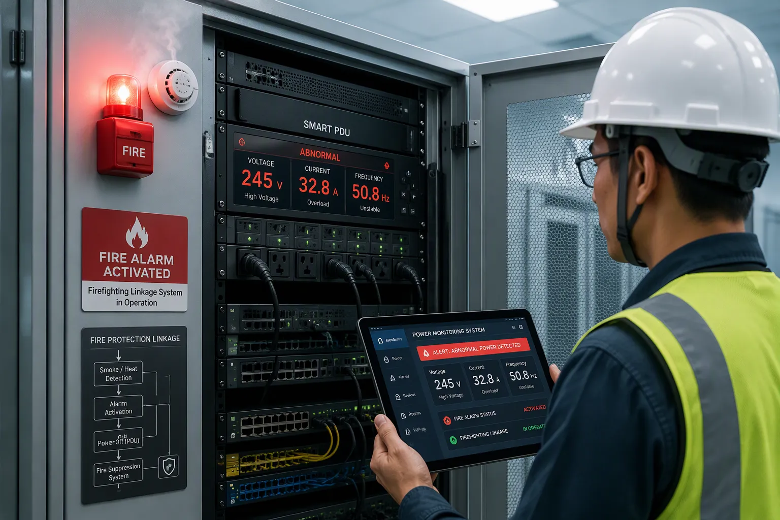
A smart pdu-firefighting system linkage triggers a fire alarm the moment it detects a power anomaly inside telecom cabinets. This mechanism runs automatically, without waiting for a technician to notice a problem on site.
You will learn three things here: how a smart PDU detects power anomalies, how those anomalies become real fire hazards, and how the linkage activates the alarm. Each step follows a clear signal path from measurement to response.
This explanation stays technical and mechanism-focused for telecom engineers and facility managers. It describes how monitoring data moves through firefighting systems, not a product pitch. You get the trigger logic you need to evaluate your own setup.
Key Takeaways
Smart PDUs monitor power and environmental data in real time to spot anomalies early.
Power anomalies like overheating and arc faults can quietly damage equipment and start fires.
The PDU sends a signal to the firefighting controller, which verifies the event and triggers alarms.
Early automatic alarms give responders time to act and reduce fire damage.
Tune thresholds and document your signal path to keep the system reliable and credible.
How Smart PDUs Detect Power Anomalies
Real-Time Power Monitoring
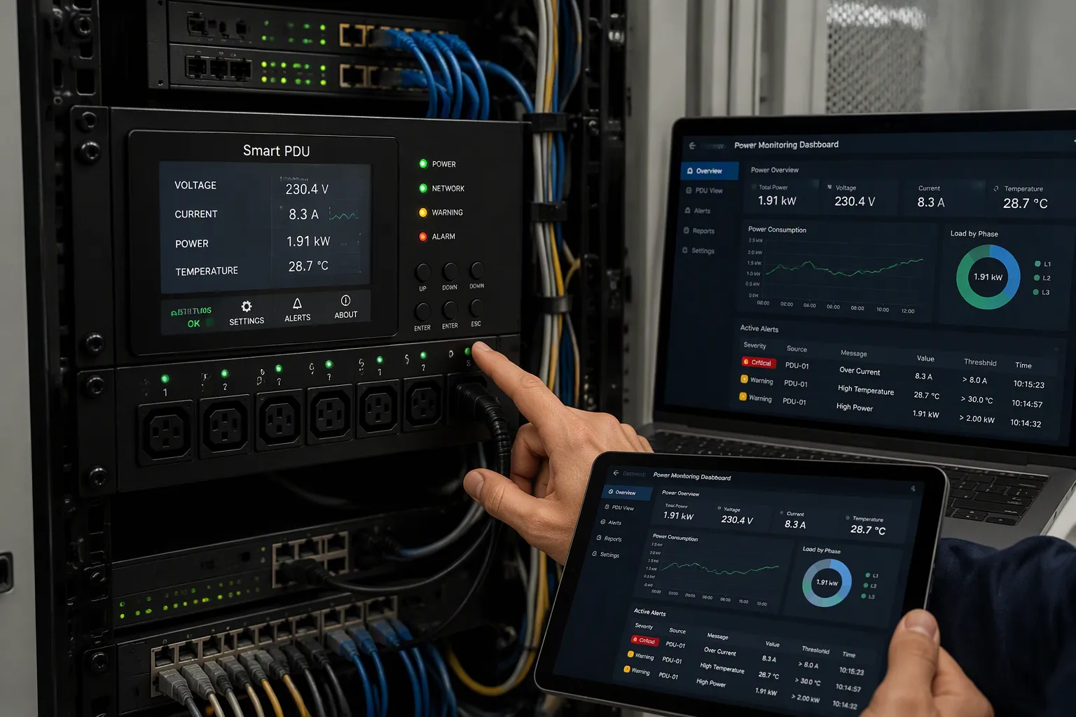
A smart PDU turns raw electrical data into a continuous stream of usable information. The ESTEL Smart Power Distribution Unit monitors voltage, current, and temperature without interruption. It shows every reading on its LCD, so you can verify values on site during maintenance or troubleshooting. This continuous real-time monitoring reveals power anomalies before they grow into failures. You gain a clear baseline for normal operation.
Real-time monitoring covers more than basic electrical parameters. The unit tracks power, energy consumption, and load level as well. It also watches temperature, humidity, and other rack-level environmental conditions. Continuous monitoring of this combination gives you a full picture of cabinet health. Each reading updates continuously, so the data reflects current conditions rather than a snapshot from hours ago.
Provides detailed, real-time monitoring of power parameters and environmental conditions.
You can list the core measurements this way:
Voltage
Current
Power
Energy consumption
Load level
Environmental readings follow the same pattern:
Temperature
Humidity
Other rack-level conditions
Real-time monitoring of these values supports better power management. You see how load distributes across outlets and where consumption climbs. That visibility helps you optimize energy use and spot abnormal power patterns before they escalate. Regular monitoring of these trends also exposes slow drift that single readings miss. These readings form the raw data that later threshold logic evaluates.
Threshold Alerts and Anomaly Classification
Raw readings alone do not trigger action. Configurable thresholds turn data into decisions. You set limits for each parameter, and the smart PDU compares every sample against them. When a value crosses its limit, the system classifies the event as a specific power anomaly type: overcurrent, overvoltage, undervoltage, or overheating.
Classification matters because each anomaly demands a different response. Overvoltage may point to a supply problem upstream. Overheating may signal a blocked airflow path or a loose connection. The PDU tags the event correctly, so your team knows what to investigate. Consistent classification also separates true anomalies from harmless fluctuations and flags recurring anomalies for review. A threshold you set too tight produces noise; one set too loose misses real risk.
Remote management extends this detection beyond the site. The unit sends real-time alerts to engineers off-site through its intelligent protocols. You receive alarm notifications on your device and can review the data remotely. This remote monitoring capability means detection does not depend on someone standing in front of the cabinet. You can adjust thresholds remotely as site conditions change.
Two supporting safeguards reduce false positives. Surge protection absorbs transient spikes that would otherwise look like overvoltage events. The dehumidifying function controls moisture, which can distort temperature readings and create abnormal patterns. Both features keep alarms tied to genuine risks. This filtering keeps the alarm channel credible for operators.
Early warnings from threshold monitoring give you time to act. A classified anomaly reaches you before it becomes a fire hazard in telecom cabinets. That early link in the chain is what makes the downstream firefighting linkage possible. Reliable detection and monitoring at this stage protects both equipment and response time. The linkage depends on clean, classified signals from this first stage.
Why Power Anomalies Matter in Telecom Cabinets
Overheating and Component Degradation
Sustained overcurrent pushes internal temperatures upward inside sealed telecom cabinets. A poor connection adds contact resistance at a terminal, and that resistance converts current into heat. The cabinet enclosure traps this heat, so temperatures climb faster than they would in an open rack. Insulation on conductors softens under sustained overheating. Connectors lose spring tension, and the looser joint raises resistance further. The cycle feeds itself. Power anomalies of this kind rarely announce themselves dramatically. They accumulate quietly across weeks of normal operation.
This degradation stays invisible from the outside. You cannot see insulation cracking or a discolored terminal through a closed door. Real-time monitoring closes that gap by tracking temperature and current trends continuously. A sudden temperature rise from localized overheating points to a failing joint before visible damage appears. Early fault detection at this stage protects both the conductor and the equipment it feeds. These conditions rank among the most common fire hazards in telecom cabinets. Left alone, the anomalies spread from one terminal to the next along a shared busbar.
Arc Faults and Short Circuits
A loose or corroded connection can break contact momentarily and restrike. Each restrike produces high energy arc faults with temperatures far above the melting point of nearby insulation. A short circuit delivers a similar burst of concentrated heat. Both events can ignite dust, cable jackets, or other combustible material inside telecom cabinets. The resulting electrical fire hazards grow with every additional load on the circuit. These fire hazards spread quickly through a shared cable bundle.
Unattended outdoor sites raise the stakes. No one stands nearby to smell smoke or hear arcing. High energy arc faults can start and stop in an instant. Detection must come from instrumentation, not human senses. Continuous monitoring of current signatures and temperature gives the system a chance to respond in seconds. That speed separates a contained event from a major loss. Reliable alarms also support broader fire prevention goals. Every minute of delay adds to the fire hazards you face and erodes electrical safety at the site.
Smart PDU-Firefighting Linkage Trigger Mechanism
Signal Transmission Between Systems
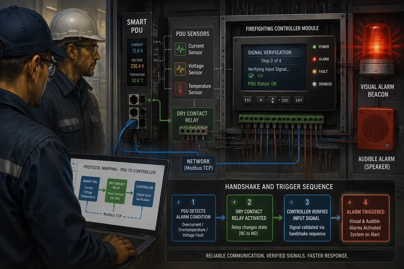
The linkage depends on a clean communication path between two separate systems. When a power anomaly crosses its configured threshold, the smart PDU sends a signal to the firefighting controller. That signal travels in one of two ways. A dry-contact output closes a relay circuit, which gives the controller a simple voltage-free contact closure. A protocol-based link carries the same event as structured data over a serial or network connection. Dry contacts suit straightforward installations. Protocol links carry richer detail, such as the anomaly type and the measured value at the moment of the event.
You should treat this path as the handshake of the whole fire alarm trigger mechanism. The PDU does not decide to suppress a fire. It reports an initiating event. The firefighting controller owns every decision that follows. Keep the two systems electrically separated through the dry contact, and document the protocol mapping when you use a data link. A mislabeled signal here defeats the entire chain.
The Fire Alarm Trigger Sequence
The sequence follows a fixed order. Each stage confirms the previous one before the next begins.
Sensors continuously monitor current, voltage, and temperature inside the cabinet.
Algorithms analyze the collected data and detect abnormal patterns.
The system flags conditions such as overheating, arcing, or overloads as fire hazards.
The PDU transmits the classified event to the firefighting controller.
The controller verifies the signal against its own logic and sensor inputs.
Visual and audible alarms activate to alert personnel on site.
Notifications go out through connected systems or mobile apps for rapid response.
The controller moves to suppression readiness, and some units shut down power automatically to prevent fire spread.
Verification at step five matters. The controller cross-checks the incoming signal against its own detection inputs. A single spurious contact closure rarely passes this check alone. This step keeps nuisance trips low without weakening real detection.
Notice where the PDU sits in this chain. It acts as the initiating event, not the suppression device. The unit detects, classifies, and reports. The firefighting system verifies, alarms, and prepares suppression. Real-time monitoring at the first stage feeds every later stage. Continuous monitoring of power anomalies in telecom cabinets gives the linkage its input, and the fire alarm follows automatically once the chain completes.
Benefits and ESTEL Implementation Considerations
Faster Response and Reduced Damage
The trigger chain pays off in time. A smart pdu classifies a power anomaly and passes it to the controller within seconds, so the alarm sounds long before smoke appears. Earlier alarm activation gives responders a head start and cuts fire damage to the cabinet and its surroundings. Critical telecom equipment survives events that would otherwise destroy line cards and power modules.
Tuned thresholds deliver a second gain. You set limits that match real site conditions, and the system ignores harmless spikes while it catches genuine anomalies. Fewer false alarms keep the alarm channel credible, so staff respond to every notification. Continuous monitoring also produces trend data you can review for fire prevention planning. That combination of speed and accuracy protects both equipment and electrical safety at unattended sites.
Planning the Integration
ESTEL supplies outdoor telecom cabinets and related equipment under ISO9001-aligned quality control, and the company can support integration planning for telecom cabinets. Treat the Smart Power Distribution Unit as one fitting option among several. Work through these steps before you order:
Confirm the power architecture. Check whether the cabinet runs on DC or external AC, because that choice dictates the PDU model family.
Map outlet requirements. Count the devices you actually power, then match the outlet count and current rating. Verify the outlet count and current rating cover the real device load without forcing parallel cabling.
Verify the alarm interface. Confirm that dry-contact relay outputs suit your fire panel, and align the wiring diagrams with the cabinet vendor's specifications.
Check the cabling. Confirm the input plug and cable length against the cabinet documentation.
Coordinate with the firefighting controller vendor. Agree on the signal type and test the handshake before commissioning.
Document every interface decision. Clear records shorten commissioning and simplify later maintenance.
A smart PDU detects a power anomaly, classifies it, and transmits a signal through the linkage. The firefighting system then verifies the event and activates the fire alarm. This chain runs automatically from measurement to response.
The value lies in early, automatic action. Fast detection of anomalies protects telecom cabinets and the equipment inside them. You reduce fire hazards before they grow into a real fire.
Review your current monitoring and linkage setup today. Confirm that your thresholds match site conditions and that your signal path is documented. ESTEL's Smart Power Distribution Unit offers one resource for implementation guidance as you plan the integration.
FAQ
How does a smart PDU signal the firefighting controller?
The PDU sends a dry-contact closure or a protocol-based signal to the firefighting controller. That signal reports the anomaly and starts the fire alarm chain.
Does the PDU suppress a fire itself?
No. The PDU acts as the initiating event in telecom cabinets. It detects and reports, while the controller verifies the event and activates the fire alarm and suppression readiness.
What power anomalies can the PDU classify?
The unit classifies overcurrent, overvoltage, undervoltage, and overheating. Real-time monitoring of voltage, current, and temperature feeds that classification, and continuous monitoring of trends exposes slow drift.
How do I reduce false alarms in the linkage?
Tune thresholds to site conditions. Surge protection absorbs transient spikes, and the dehumidifying function controls moisture. Review monitoring data regularly to separate real anomalies from noise.
What should I check before integrating a PDU with my fire panel?
Confirm the outlet count and current rating cover the real device load, and verify the input plug and cable length against the cabinet documentation. Agree on the signal type with your firefighting controller vendor and test the handshake before commissioning.
See Also
Ensuring Reliable Power Supply For Telecom Cabinets
Understanding ESTEL PDUs And Their Data Center Cabinet Role
Installing And Maintaining Smoke Sensors In Communication Cabinets
Photovoltaic Energy Storage Power Systems For Telecom Cabinets
Why Telecom Cabinets Use -48VDC Voltage And Grounded Positive Terminal
CALL US DIRECTLY
86-13752765943
3A-8, SHUIWAN 1979 SQUARE (PHASE II), NO.111, TAIZI ROAD,SHUIWAN COMMUNITY, ZHAOSHANG STREET, NANSHAN DISTRICT, SHENZHEN, GUANGDONG, CHINA
