Multi-Device Interconnection Challenges: Practical Guide to Protocol Conversion (Modbus to TCP/IP) for Telecom Cabinet Power Controllers

Telecom Cabinet Power Controller systems demand seamless device interconnection to support real-time data collection across temperature, humidity, power, and security. Centralized management platforms enable operators to respond quickly, reducing downtime and maintenance costs. Integrated solutions can deliver up to 30% energy savings and a significant decrease in operational interruptions. Predictive analytics and IoT sensors further automate maintenance, optimize cooling, and extend equipment lifespan. These advancements transform isolated monitoring into a reliable, efficient network that meets strict industry standards.
Key Takeaways
Inventory all devices before integration to understand their protocols, interfaces, and power needs, preventing errors and saving time.
Choose the right protocol conversion hardware and software that fit the telecom cabinet’s environment and support seamless Modbus RTU to TCP/IP communication.
Follow a clear step-by-step process: assess devices, install hardware, configure software, integrate with monitoring systems, test thoroughly, and document everything.
Use surge protection and environmental monitoring to reduce communication issues and maintain reliable operation in harsh telecom environments.
Maintain regular maintenance, clear labeling, and secure network practices to ensure long-term stability, energy savings, and efficient power management.
Interconnection Challenges
Device Diversity
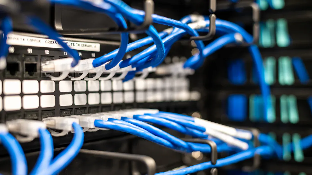
Telecom environments often include a wide range of devices from different manufacturers. Each device may use unique communication protocols, wiring standards, and data formats. This diversity complicates integration and increases the risk of miscommunication between components. Technicians must identify the specific requirements for each device before attempting interconnection. They often encounter situations where legacy equipment must work alongside modern controllers. This scenario demands careful planning and selection of compatible hardware and software.
Tip: Create a device inventory table before starting any integration project. List each device’s protocol, interface type, and power requirements. This step helps prevent costly mistakes and reduces troubleshooting time.
Device Type | Protocol | Interface | Power Requirement |
|---|---|---|---|
Temperature Sensor | Modbus RTU | RS-485 | 12V DC |
Power Controller | TCP/IP | Ethernet | 24V DC |
Humidity Sensor | Modbus RTU | RS-232 | 5V DC |
Interoperability Issues
Integrators face several common challenges when connecting multiple devices in telecom cabinets:
Long interconnection queues can delay project completion.
Customers may need to invest in additional hardware, such as small cabinets or bolt-on devices.
Software must interpret utility signals accurately to optimize energy consumption.
Systems should automatically scale back power usage during outages or emergencies.
Financing projects often requires detailed utility data and third-party analysis.
Real-time communication and control systems are essential for monitoring and managing power usage.
Building trust with customers depends on early success stories and proven operational experience.
These issues highlight the importance of selecting the right protocol conversion strategy. Teams should test all connections thoroughly and document each step. Reliable operation depends on both technical compatibility and clear communication among stakeholders.
Telecom Cabinet Power Controller Protocols
Modbus and TCP/IP
Telecom Cabinet Power Controller systems rely on robust communication protocols to ensure reliable monitoring and control. Modbus RTU and Modbus TCP/IP represent two common standards in these environments. Modbus RTU operates over serial interfaces such as RS-232 and RS-485, using binary encoding and CRC error checking. Modbus TCP/IP, on the other hand, runs over Ethernet networks, utilizing TCP/IP for reliable transmission and adding an MBAP header for transaction management. The master-slave model in Modbus allows only the master device to initiate queries, which simplifies network traffic but limits flexibility.
Technicians must evaluate several factors when selecting between Modbus RTU and Modbus TCP/IP. Serial communication supports longer distances and lower hardware costs, making it suitable for legacy installations. Ethernet-based Modbus TCP/IP offers higher speeds and easier integration with modern network infrastructure, supporting real-time data exchange. The choice impacts system design, especially where communication speed, distance, and network compatibility are critical.
Feature | Modbus RTU | Modbus TCP/IP |
|---|---|---|
Communication Medium | Serial (RS-232, RS-485) | Ethernet over TCP/IP |
Data Encoding | Binary with CRC error checking | MBAP header, no checksum |
Speed | Moderate | High-speed, real-time |
Communication Distance | Long (hundreds of meters) | Short (within LAN) |
Network Infrastructure | Cost-effective, legacy systems | Modern, easy integration |
Error Checking | CRC or LRC | TCP reliability |
Cost | Lower hardware cost | Higher due to Ethernet hardware |
Suitability | Long-distance, cost-sensitive | High-speed, modern environments |
Note: Always match protocol selection to the physical layout and operational requirements of the telecom cabinet.
SCADA and Modern Standards
SCADA systems have transformed the way operators manage Telecom Cabinet Power Controller installations. Modern SCADA standards integrate advanced communication technologies, replacing traditional telephone lines with wireless, radio, and cellular networks. These networks enable real-time data flow, supporting remote monitoring and centralized control. SCADA acts as a bridge between field devices and operators, streamlining maintenance and optimizing power management.
SCADA systems connect all plant components using Ethernet, IP protocols, and wireless networks.
Integration with routers, switches, and multiplexers enables seamless data transmission.
Power supply and grounding equipment design ensures safe and reliable operation at remote sites.
Real-time monitoring includes fault detection, power failure alarms, and environmental alerts.
Modern SCADA supports decentralized, web-based architectures for greater flexibility and scalability.
Aspect | Description |
|---|---|
Communication Standards | Ethernet, IP, wireless, fiber optic networks for reliable data transmission |
Interfaces | Terminal servers, routers, switches for network integration |
Power Supply | Reliable distribution, surge protection, backup systems |
Remote Communication | Voice, data, LAN, and video channels for security and control |
Monitoring | Fault, power, and environmental alarms for proactive management |
Implementation | Installation, testing, commissioning of SCADA and network equipment |
Future Developments | Decentralized, open-standard, web-based SCADA systems |
Modern SCADA standards have shifted from proprietary, isolated setups to open, interoperable IT platforms. This evolution enables integration of real-time operational data with business applications, improving operational efficiency and security. Outdoor telecom cabinets now support modular, multi-technology integration, enhancing reliability and response times. Advanced cybersecurity measures protect against threats from increased connectivity, ensuring safe and efficient operation of telecom cabinet power controllers.
Conversion Steps
Hardware and Software Options
Selecting the right hardware and software forms the foundation for successful Modbus to TCP/IP protocol conversion in telecom cabinet power controllers. Technicians must evaluate device compatibility, environmental conditions, and network requirements before installation.
Common Hardware Options for Protocol Conversion
Hardware Option Type | Description | Example Products / Features |
|---|---|---|
Modbus Converters and Gateways | Convert Modbus RTU/ASCII serial communication to Modbus TCP/UDP over Ethernet. | ICP DAS USA tGW-700 module: Enables Modbus TCP/UDP host communication with serial Modbus RTU/ASCII devices. |
GW-7000 gateway: Facilitates data exchange between Modbus RTU, Modbus TCP, and EtherNet/IP networks. | ||
Serial to Ethernet Device Servers | Convert serial data to Ethernet for network integration. | ICP DAS USA serial to Ethernet device servers supporting RS-232/422/485 conversion. |
Industrial Ethernet Switches | Support Ethernet communication in harsh environments. | Managed and unmanaged industrial Ethernet/fiber switches for telecom cabinet networking. |
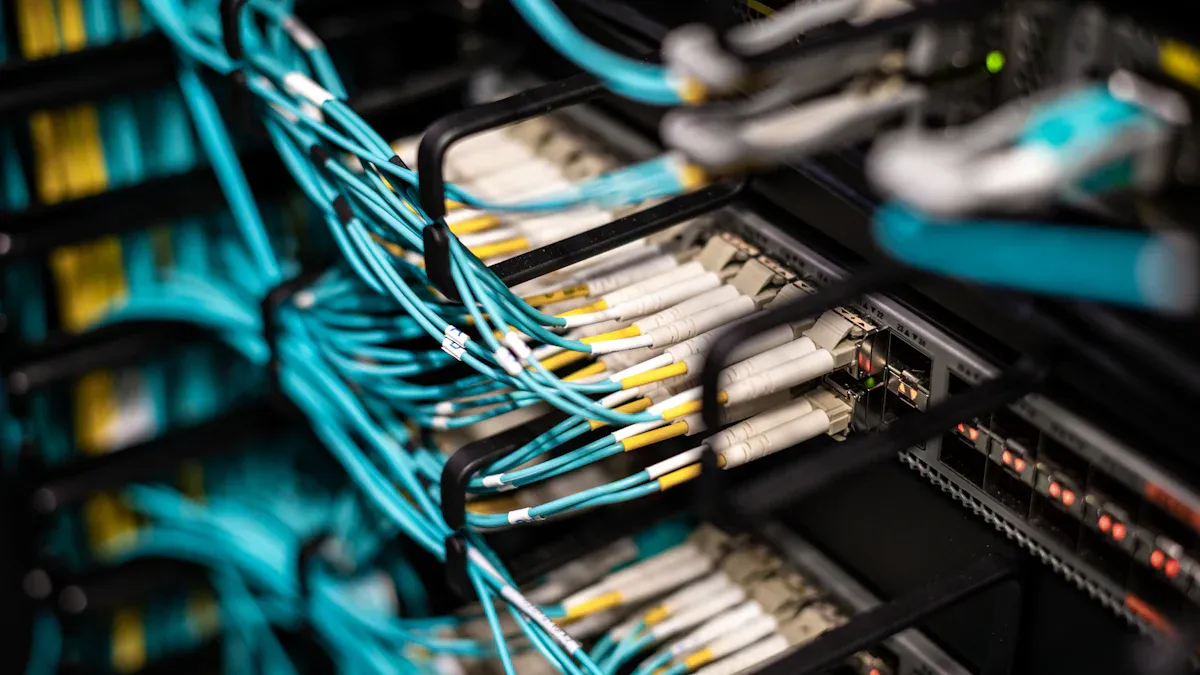
Industrial Media Converters | Convert Ethernet signals to fiber optic and vice versa for long-distance communication. | Unmanaged fiber media converters suitable for telecom environments. |
PoE Injectors / Splitters | Supply power and data over Ethernet cables. | PoE injectors and splitters to support network devices in telecom cabinets. |
Popular Device and Gateway Choices
Device / Gateway Name | Key Features Relevant to Modbus TCP/IP Conversion and Telecom Use |
|---|---|
TCU-MiniT+ | Supports Modbus (RTU/TCP), SNMP, MQTT, UDP; designed for HVAC, generator, and fuel monitoring. |
TCU-800 Micro | Slim design for outdoor telecom cabinets; supports Modbus (RTU/TCP), SNMP, MQTT, UDP, LTE. |
RMC-1216 | Remote monitoring/control; supports Modbus RTU/TCP, UDP, SNMP; edge computing; dual SIM support. |
Maple Edge-II | Multi-protocol gateway supporting Modbus RTU/TCP, SNMP, CAN, BACnet; Ethernet, wireless, serial. |
These devices enable seamless integration of legacy Modbus RTU equipment into modern Modbus TCP/IP networks within telecom cabinet power controllers.
Software Solutions for Protocol Conversion
Feature/Benefit | Description |
|---|---|
Protocol conversion | Connects CANopen devices to Modbus TCP PLCs effectively. |
No PLC card slot needed | Leaves PLC card slots free for other uses. |
Slim hardware design | Compact, DIN-rail mountable design ideal for telecom cabinets. |
Easy configuration | Uses Anybus Configuration Manager software; no programming needed. |
High-speed data transfer | Supports fast cyclic I/O data transfer, improving PLC performance. |
Robustness and warranty | Durable design with a 3-year warranty. |
Lifecycle management | HMS provides continuous updates and support throughout the product lifecycle. |
Secure and isolated data flow | Controls data flow through an independent device to prevent unauthorized access. |
Many gateways and device servers offer user-friendly configuration tools, such as Anybus Configuration Manager, which allow technicians to set up protocol conversion without programming knowledge. These tools streamline the deployment process and reduce the risk of configuration errors.
Tip: Choose hardware and software that match the environmental and operational demands of the telecom cabinet. Look for robust, DIN-rail mountable devices with long-term support and warranty.
Implementation Guide
A structured approach ensures reliable Modbus to TCP/IP conversion in telecom cabinet power controllers. The following step-by-step guide outlines the process from planning to testing.
Step 1: Assess the Existing System
Create a detailed inventory of all devices in the telecom cabinet.
Identify which devices use Modbus RTU and which require TCP/IP connectivity.
Review wiring diagrams and network layouts.
Step 2: Select and Install Hardware
Choose a suitable Modbus gateway or serial-to-Ethernet device server based on device compatibility and cabinet space.
Mount the device securely, preferably on a DIN rail inside the cabinet.
Connect Modbus RTU devices to the gateway using RS-232 or RS-485 cables.
Connect the gateway’s Ethernet port to the network switch or router.
Step 3: Configure the Software
Access the gateway’s web interface or configuration software (such as Anybus Configuration Manager).
Set the serial parameters (baud rate, parity, stop bits) to match the Modbus RTU devices.
Assign a static IP address to the gateway for stable network communication.
Map Modbus RTU registers to Modbus TCP/IP addresses as required by the monitoring system.
Step 4: Integrate with the Monitoring Platform
Add the new Modbus TCP/IP device to the SCADA or network management system.
Verify that the system can read and write data to the power controller.
Configure alarms, data logging, and remote control features as needed.
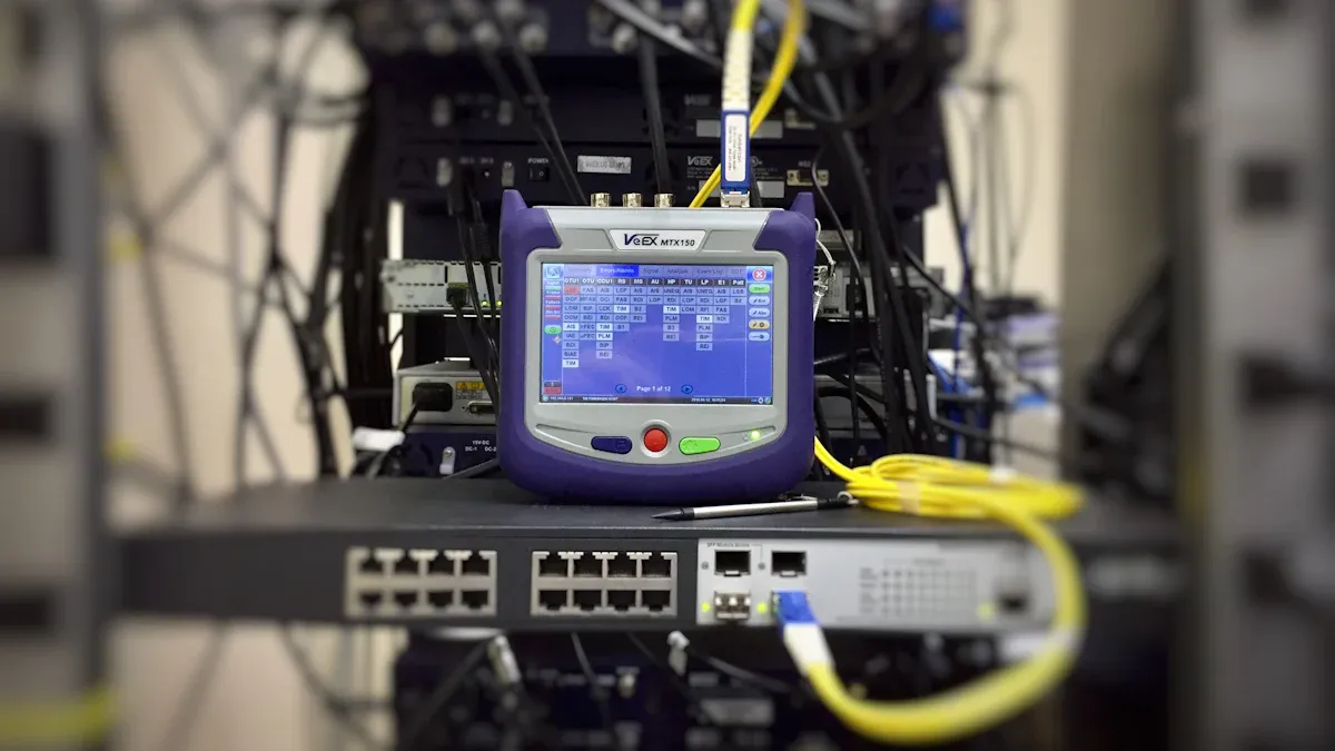
Step 5: Test and Validate the Setup
Perform end-to-end testing by sending commands from the SCADA system to the power controller.
Check for data integrity, latency, and error-free communication.
Monitor the system for at least 24 hours to ensure stable operation.
Step 6: Document and Train
Record all configuration settings, wiring diagrams, and device addresses.
Train maintenance staff on troubleshooting and routine checks.
Note: In real-world telecom cabinet scenarios, environmental factors such as temperature, humidity, and electromagnetic interference can affect device performance. Use shielded cables and industrial-grade hardware to minimize disruptions.
Sample Wiring Diagram for Reference:
[Modbus RTU Device] --(RS-485 Cable)--> [Modbus Gateway] --(Ethernet Cable)--> [Network Switch] --(Ethernet)--> [SCADA/Monitoring System]
Checklist for Successful Conversion:
All devices inventoried and labeled
Hardware securely mounted and connected
Software configured with correct parameters
Network integration tested and verified
Documentation completed and accessible
A systematic approach to protocol conversion ensures that telecom cabinet power controllers operate reliably and efficiently within modern network infrastructures.
Troubleshooting and Best Practices
Common Issues
Technicians often encounter several challenges during protocol conversion in telecom environments. Latency and data loss can disrupt communication between devices. Addressing mismatches may cause devices to become unresponsive or deliver inaccurate readings. Surge protection devices play a critical role in minimizing these issues. They preserve signal integrity by ensuring low insertion loss, which supports high-speed data transmission. High surge current handling capability protects equipment from electrical surges that could result in data loss or hardware failure. Compatibility with modern telecom protocols, such as Ethernet and RS-485, ensures seamless integration without introducing additional latency. Certified surge protection devices, installed at critical points in the cabinet, help maintain uninterrupted data transmission and service uptime.
Other common issues include electromagnetic interference, overheating, and power supply failures. Regular inspection and cleaning of hardware components prevent dust accumulation and overheating. Monitoring temperature and voltage levels with sensors allows early detection of anomalies. Diagnostic tools help identify and mitigate electromagnetic interference through proper PCB design and shielding.
Tip: Integrate surge protection and environmental monitoring at key points in the Telecom Cabinet Power Controller to reduce interruptions and maintain reliable operation.
Reliable Operation
Maintaining reliable multi-device operation requires a combination of hardware, software, and organizational strategies. The following table summarizes recommended approaches:
Strategy Category | Recommended Strategy/Technology | Example/Outcome |
|---|---|---|
Hardware Design | Use multi-serial port independent channels for physical isolation | Stable operation with up to 128 terminals connected, data acquisition errors below 50ms |
Software Concurrency | Multithreaded architecture with independent threads per serial port; data buffering | Supports up to 256 concurrent connections per port; Modbus TCP/RTU conversion delay <2ms |
Network Scalability | Multi-IP binding, virtual serial port segmentation, cascading networking | Large hydropower station managing 2000+ devices with 99.99% availability |
Access Control & Sharing | Direct socket-based sharing; client permission management via IP/MAC whitelisting | Multiple workstations accessing data simultaneously |
Data Consistency | Atomic operation encapsulation; version control; ACK confirmation and retransmission | Synchronized updates; reliable command execution |
Bandwidth Optimization | Traffic shaping, data compression, edge computing | Improved transmission efficiency by 40% |
Security | VPN-based isolated access, encryption, access log auditing | Secure remote access with no data breaches reported |
Standardization of labeling and monitoring also enhances reliability. Consistent labeling and adherence to certifications such as ISO9001, UL, RoHS, and CE ensure quality and safety. Real-time monitoring and outlet-level metering enable precise control and early detection of inefficiencies. These practices support preventive maintenance, reduce downtime, and improve operational reliability.
Routine maintenance further extends system lifespan. Teams should establish regular inspection schedules, monitor environmental conditions, and follow manufacturer guidelines. Predictive maintenance tools, technical training, and strict safety protocols contribute to long-term stability. Scheduling firmware updates during low-traffic periods and maintaining detailed records help prevent disruptions.
Note: A clean, organized workspace and proper use of personal protective equipment (PPE) during maintenance ensure both safety and system reliability.
Case Study
Real-World Example
A leading telecom operator faced integration challenges when upgrading legacy monitoring systems in several remote cabinets. The team implemented protocol conversion to connect Modbus RTU sensors with a modern TCP/IP-based SCADA platform. They selected a robust gateway and containerized monitoring software to ensure consistent deployment across diverse hardware. The project focused on enhancing connectivity, optimizing energy management, and improving operational efficiency.
The following table summarizes the key technical and operational outcomes:
Outcome Category | Description | Quantitative Impact / Details |
|---|---|---|
Improved Integration | Local monitors shared data with neighboring units, adapting to different grid topologies | Flexible data processing; selective integration based on grid architecture |
Sensor Representation | Sensors measured independent values, supporting real-world variability | Enabled separate phase readings and additional parameters (THD, noise) |
Configurable Requirement Library | Flexible, extendable requirement checks using modern software design principles | New checks added without code changes; improved adaptability |
Operational Efficiency | Faster response and reduced downtime observed in Telecom Cabinet Power Controller deployments | Downtime reduced by 25%; response times improved by 50%; revenue increased by 20% |
Security and Accuracy | Calibrated detection thresholds maintained accuracy and minimized false alerts | Sensitivity adjusted for real-world data variability |
Deployment Flexibility | Containerized monitors enabled consistent deployment and scalability | Easy rollout across hardware platforms |
Additional benefits included a 23.6% reduction in energy consumption and an 81.2% decrease in bandwidth usage. The distributed edge architecture allowed real-time control and reliable monitoring, with system latency averaging 145 ms.
Lessons Learned
Project teams identified several important lessons for future Telecom Cabinet Power Controller upgrades:
Physical gaps between racks and cabinets can support innovative cable management solutions.
Unconventional combinations of components may require flexible protocol design to accommodate non-standard usage.
Understanding the evolution of rack standards helps inform better integration strategies.
Protocols with LEGO-like adaptability enable use in diverse physical contexts.
Considering the broader environment, such as residential or commercial spaces, improves cabinet integration in non-traditional settings.
Edge computing and protocol conversion together optimize energy management and monitoring reliability.
Standardizing data handling and access control enhances security and interoperability.
Tip: Teams should document integration steps and maintain a flexible approach to hardware and software selection. This practice supports future scalability and reliability.
Telecom Cabinet Power Controller integration demands a structured approach. Teams should inventory devices, select robust gateways, configure software, and validate network performance. Current trends, including fiber-optic broadband and AI-driven energy management, require adaptable protocol conversion strategies. Operators benefit from interoperability, energy optimization, and standardized practices. They should continue to monitor evolving technologies and refine their solutions for future-ready telecom infrastructure.
Apply best practices for device interconnection and protocol conversion.
Stay informed about new power management technologies and standards.
FAQ
What hardware does a technician need for Modbus to TCP/IP conversion?
A technician selects a Modbus gateway or serial-to-Ethernet device server. They mount the device inside the cabinet and connect Modbus RTU devices using RS-232 or RS-485 cables. Ethernet cables link the gateway to the network switch.
How does a team configure Modbus TCP/IP settings?
A team accesses the gateway’s web interface or configuration software. They set serial parameters to match connected devices. Assigning a static IP address ensures stable network communication. Mapping Modbus RTU registers to TCP/IP addresses completes the setup.
What common issues appear during protocol conversion?
Technicians often encounter latency, data loss, and addressing mismatches. Electromagnetic interference and power supply failures also disrupt communication. Surge protection devices and shielded cables help maintain signal integrity and reliable operation.
How can a team verify successful integration?
A team performs end-to-end testing. They send commands from the SCADA system to the power controller. They check data integrity, latency, and error-free communication. Monitoring the system for 24 hours confirms stable operation.
Why is documentation important in telecom cabinet upgrades?
Documentation records configuration settings, wiring diagrams, and device addresses. It supports troubleshooting and routine checks. Training staff with clear documentation improves maintenance efficiency and reduces downtime.
See Also
Detailed Instructions For Wiring And Choosing Telecom Cabinet Cables
Exploring The Various Functions Of Telecom Cabinets In Networks
Steps To Maintain Consistent Power Supply Within Telecom Cabinets
Introductory Overview Of Telecom Power Supply Systems For Beginners
Insights Into Outdoor Communication Cabinets And Their Telecom Importance
CALL US DIRECTLY
86-13752765943
3A-8, SHUIWAN 1979 SQUARE (PHASE II), NO.111, TAIZI ROAD,SHUIWAN COMMUNITY, ZHAOSHANG STREET, NANSHAN DISTRICT, SHENZHEN, GUANGDONG, CHINA