Anti-Corrosion Design for High Salinity and Pressure in Subsea Telecom

You face a brutal reality when you design subsea telecom repeater stations. High salinity and crushing pressure attack every exposed surface. Corrosion protection demands an integrated strategy. You combine material selection, protective coatings, cathodic protection, and continuous monitoring. A single corrosion-induced failure severs the signal, triggers costly repairs, and risks environmental harm. Subsea repeaters sit at intervals along the cable. Landing stations power each one, so reliability is non-negotiable. Advanced corrosion control extends cable life and reduces failure rates over long routes. ESTEL builds robust telecom power systems for these harsh subsea environments. What does it take to design repeater station power systems that resist saltwater corrosion for decades?
Key Takeaways
Combine resistant materials, protective coatings, and cathodic protection to block saltwater corrosion.
Choose titanium or duplex stainless steel for long-lasting repeater housings.
Use natural cooling power systems to avoid salt-laden air and reduce corrosion risk.
Monitor corrosion with sensors and remote diagnostics to catch problems early.
Invest in anti-corrosion design to extend cable life beyond 25 years and cut failures.
Subsea Cable Corrosion Background and Mechanisms
Electrochemical Corrosion in High-Salinity Seawater
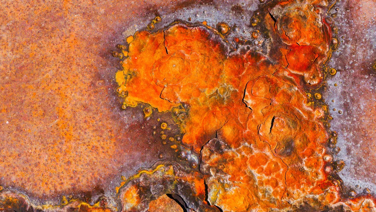
Seawater acts as a powerful electrolyte. High salinity accelerates electrochemical reactions on repeater housings and power feed conductors. These metal surfaces endure continuous exposure to saltwater. You must understand this chemistry before selecting materials.
Corrosion begins when metal ions dissolve into the surrounding water. Dissimilar metals in contact create galvanic corrosion at junction points. You often see this between housing sections and cable connectors. Pitting corrosion forms small holes that penetrate deep into structural walls. Microbiologically influenced corrosion adds another danger. Bacterial colonies alter local chemistry and consume protective oxide layers.
These mechanisms interact. A tiny coating defect becomes a pitting site within weeks. The attack then spreads damage outward from that point.
The subsea cable corrosion background extends to the earliest submarine cable deployments, when engineers laid the first cables across waterways. Those early systems failed within months, undone by prolonged saltwater exposure. Today, similar cables encircle the globe. Engineers learned that saltwater corrosion demanded continuous barrier protection, not simply thicker metal walls.
Pressure Effects on Material Degradation
Hydrostatic load compounds the chemical attack. Extreme depth-related pressure variations stress every seal and coating. You cannot separate depth effects from chemical degradation.
Compressive forces drive water into microscopic coating gaps. Penetrated water remains trapped between the coating and the metal substrate. The trapped moisture accelerates degradation from the inside out. Seal performance degrades under cyclic depth loading, creating fresh intrusion paths.
Material fatigue accelerates as well. Depth cycling induces micro-cracking in protective layers. Those cracks expose bare metal to corrosive marine environments. Together, these factors create current corrosion challenges in saltwater environments that surface gear never encounters.
You need alloys that resist both chemical and mechanical attack. Titanium and duplex stainless steel deliver proven performance. Their higher cost pays off through decades of reliable service in subsea cable systems.
Proactive corrosion protection at the design stage eliminates most failure modes. You engineer for the full depth range, not just the average operating depth. This approach keeps your subsea installation reliable for decades in subsea conditions.
Core Principles of Corrosion Control for Subsea Cables
Material Selection for Corrosion Resistance
You start with the metal itself. Titanium and duplex stainless steel resist saltwater attack far better than standard carbon steel. Titanium forms a stable oxide film that repairs itself when scratched. Duplex stainless steel combines high strength with strong resistance to pitting and stress corrosion cracking. These alloys carry real trade-offs. Titanium costs significantly more and demands specialized machining techniques. Duplex stainless steel offers a middle ground, though welding requires careful control to preserve its corrosion-resistant microstructure.
Material choice also affects galvanic corrosion risk. When you join dissimilar metals, the less noble metal becomes the anode and dissolves. You must select compatible alloys or insert insulating barriers at every junction. This principle applies across all subsea cable systems, from repeater housings to power feed conductors.
Barrier Layers and Cathodic Protection
Materials alone cannot stop corrosion. You add barrier layers to isolate metal from the surrounding seawater. Epoxy coatings bond tightly to prepared surfaces and block electrolyte contact. Polyethylene jacketing provides a thick, durable outer shield against abrasion and chemical attack. Hermetic seals close every penetration point where cables enter the housing. A single unsealed gap admits water and starts the degradation process.
Cathodic protection optimization complements these barriers. You connect sacrificial anodes made from zinc or aluminum alloys to the structure. These anodes corrode preferentially and protect the steel components. Impressed current systems offer another option for larger installations. A controlled direct current shifts the metal's electrochemical potential into a protected range. This method requires continuous power and careful monitoring.
For repeater station power components, you need equipment that minimizes internal stress. Heat and voltage fluctuation accelerate corrosion at connection points. ESTEL's Telecom Power System addresses this challenge directly. The system uses natural cooling, which eliminates fan-induced vibration and reduces thermal cycling. Its wide input voltage range handles unstable supply conditions without straining internal components. These design choices lower the mechanical and thermal stress that worsen corrosion in subsea environments.
You combine these principles into a layered defense. Alloys provide the structural foundation. Barriers block the electrolyte. Cathodic protection neutralizes electrochemical activity at exposed sites. Each layer supports the others, and no single method works alone. This integrated approach defines effective corrosion control for subsea cables. It also extends to high-voltage power transmission systems, where similar material and protection strategies apply.
Existing Corrosion Control Solutions for Subsea Cables
Engineers have refined these protections over many decades. These subsea systems combine external armoring, multi-layer coatings, elastomeric seals, and resilient housings. You apply every layer because each one blocks a distinct failure path. No single technology provides complete protection.
Armoring, Coatings, and Seals
Steel wire armor offers a hard physical barrier against abrasion and impact. Galvanization protects the wire, but it can still degrade in highly acidic or saline environments. Synthetic glass yarn armoring resists chemical breakdown, yet it lacks a hard surface for mechanical wear. The table below compares both options in detail.
Property | Steel Wire Armoring | Synthetic Glass Yarn Armoring |
|---|---|---|
Corrosion resistance | Galvanization provides protection, but the material can still degrade in highly acidic or saline environments. | The glass fiber layer itself does not degrade; however, if the outer jacket is breached and water enters, long-term waterproofing must be ensured by design. |
Provides a hard physical barrier; when paired with a PA12 nylon jacket, surface abrasion resistance is significantly enhanced. | Relies on the outer jacket for surface abrasion resistance; the yarn layer alone does not offer a hard physical barrier against mechanical wear. | |
Chemical durability | Can be compromised in high-corrosion or chemical-exposure environments unless combined with a protective outer layer such as PA12 nylon. | The PA12 nylon jacket's chemical and oil resistance is the primary protective driver in corrosive or chemical-exposure environments. |
Abrasion Resistance. Ability of a wire, cable or material to resist surface wear.
Above the armor, you build a multi-layer coating system. Epoxy primer bonds to cleaned metal and blocks electrolyte contact. Polyethylene jacketing provides a thick water-resistant shield. PA12 nylon supplies strong chemical and oil resistance. Elastomeric seals then close every cable penetration into a repeater housing. One seal failure lets saltwater contact live metal, so you must design seals for both temperature cycling and static load.
Pressure-Tolerant Housing Designs
Chemical barriers alone cannot manage deep-water force. You need pressure resistance built into the housing geometry. An oil-filled housing uses dielectric oil to equalize external load, reducing the differential that would crush the enclosure. A balanced enclosure uses a flexible membrane to transfer that load to a compensating fluid. Hermetic feedthroughs pass power and signals through the hull without creating an intrusion path.
These designs protect submarine repeaters directly. A submarine repeater can rest at great depths, where cyclic depth changes crack protective layers. Corrosion protection depends on alloy selection, coatings, and cathodic protection. This geometry prevents cracks that expose bare metal to seawater.
You must also adapt terrestrial power systems for this environment. Standard telecom rectifiers use fans and open vents. Fans draw salt-laden air across live terminals, accelerating galvanic corrosion. For subsea cable systems, avoid active cooling. Submarine optical links demand exactly this adaptation. ESTEL's Telecom Power System uses natural cooling and accepts a wide range of input voltages. This reduces thermal and mechanical stress inside the sealed housing.
Armoring, coatings, seals, and balanced housings work together as the complete backbone of corrosion mitigation solutions for long-haul submarine links. You cannot trust one barrier alone. Each layer keeps the electrolyte away from live metal for decades of subsea service.
Monitoring and Early Detection of Corrosion
Sensor Systems for Corrosion Tracking
You cannot inspect a repeater housing by hand at deep-water depths. You rely on sensors that watch the metal continuously. Electrochemical sensors measure small current flows at the metal surface. A rising current tells you that corrosion protection has weakened at that spot. Fiber-optic strain gauges detect the tiny dimensional changes that pitting produces. Acoustic emission monitoring listens for the sharp signals that cracking and coating breakdown release. Together, these tools give you real-time corrosion monitoring across the entire cable route.
Each sensor type catches a different failure mode. Electrochemical probes respond to galvanic corrosion at dissimilar-metal joints. Acoustic sensors pick up the early stages of microbiologically influenced corrosion, where bacterial colonies disturb the surface. Strain gauges reveal pressure-driven fatigue before a crack opens. You place these sensors at known weak points, such as feedthroughs and splice housings. The data then feeds into your maintenance plan long before a leak becomes critical.
Remote Diagnostics and Maintenance Planning
Landing stations give you a powerful diagnostic window. You track power feed voltage and current across every segment. A small drop in insulation resistance often signals water intrusion at a distant repeater. You correlate that anomaly with sensor data to confirm a corrosion event. This remote approach turns raw electrical readings into actionable maintenance decisions.
Branching units let you reconfigure system power from shore. When diagnostics flag a fault, you isolate the affected leg and keep the rest of the network running. This capability limits the reach of corrosion-induced failures and protects service to thousands of users. You schedule repairs during planned maintenance windows instead of reacting to sudden outages. Subsea operators who combine sensor data with remote diagnostics catch problems early. That discipline keeps repeaters alive for decades in saltwater.
Case Studies in Subsea Telecom Corrosion Control
Deep-Water Repeater Station Deployments
You can study mature examples of subsea cable corrosion control on transoceanic cable routes. Operators placed repeater stations at great depths. They integrated titanium housings, multi-layer coatings, and sacrificial anodes from the start. Many stations stayed in service for long periods. This outcome proves that layered defense outperforms a single solution.
Industry leaders advanced this design logic. Their engineers refined pressure-balanced enclosures and hermetic feedthroughs. Those components resist saltwater intrusion and depth cycling. Deep-water deployments require this combination because no single seal can block the environment forever. You protect the system by making each layer redundant.
Repeaters survive longest when you isolate every junction. Cable-to-housing connections fail first without galvanic isolation. Insulating sleeves and compatible alloys prevent dissimilar-metal attack before it starts. Real deployments demonstrate that attention to these small interfaces extends service life.
ESTEL-Supported Subsea Power Projects
ESTEL applies the same philosophy to telecom power systems that support subsea-adjacent infrastructure. You might expect a land-based cabinet to face less hostility than a repeater hull. Coastal installations still endure salt-laden air and high humidity. ESTEL adapts its Telecom Power System for these locations with sealed cabinets and protective powder coating. The coating blocks moisture and coastal spray from reaching the metal surface.
The system's natural cooling design reduces another risk. Fan-driven cooling pulls salty air across live terminals, accelerating degradation. By eliminating fans, ESTEL keeps internal components dry and thermally stable. Its wide input voltage range lowers electrical stress at connections. Less stress means fewer micro-cracks in protective finishes.
These projects show a practical path. You can extend protection beyond the wet subsea segment to the shore stations that power it. When enclosures, rectifiers, and power feeds share the same protective mindset, the entire subsea link becomes more reliable. That integrated approach matches what deep-water repeater stations have proven: planned protection pays off over decades.
Regulatory and Standards Compliance
Key Industry Standards for Subsea Equipment
You cannot deploy equipment in the ocean without meeting strict international standards. A framework standard for fiber optical submarine cable systems equipped with scientific sensors provides the design and operational requirements for subsea cable systems that carry both telecom traffic and sensor data. It addresses the unique challenges of integrating sensing elements into repeater housings without compromising structural integrity.
A quality management standard governs quality control for telecom power systems. ESTEL follows this standard throughout production. Every cabinet, rectifier, and power distribution unit passes through documented quality checks. This discipline ensures that protective coatings, seal materials, and alloy compositions meet specification before shipment. You gain confidence that each component will perform in saltwater environments.
Certification and Testing Requirements
You must prove your design survives the ocean before you commit it to the seabed. Salt spray testing exposes enclosures to a continuous 5% sodium chloride fog at +95 °F with a pH range of 6.5 to 7.2. This accelerated test follows MIL-STD-810H Method 509.6. Test durations typically run from 48 to 500 hours. You evaluate organic coatings for blistering, rusting, or adhesion loss per ASTM D714 and ASTM D3359. Dissimilar metal interfaces must show no galvanic corrosion. Platings must resist white corrosion. Anodized aluminum must show no pitting. Electrical connectors must maintain contact resistance.
Parameter | Specification |
|---|---|
Test Method | MIL-STD-810H Method 509.6 – Salt Fog |
Fog Composition | Continuous 5% sodium chloride (NaCl) fog |
pH Range | 6.5 – 7.2 |
Temperature | +95 °F |
Test Durations | Typically 48 to 500 hours |
Acceptance – Organic Coatings | No blistering, rusting, or adhesion loss (ASTM D714, ASTM D3359) |
Acceptance – Dissimilar Metals | No galvanic corrosion at interfaces |
Acceptance – Platings | No white corrosion of zinc or cadmium platings |
Acceptance – Anodized Aluminum | No pitting |
Acceptance – Electrical Connectors | No contact resistance degradation at unplugged connectors |
Pressure cycling simulates the repeated depth changes that subsea hardware endures. Long-term immersion trials verify that materials resist corrosion over extended periods. These tests confirm that your subsea equipment meets the reliability targets that operators demand.
Life Cycle Cost Analysis for Anti-Corrosion Design
Comparing Corrosion-Resistant vs. Standard Materials
You pay more upfront for titanium and duplex stainless steel. Standard carbon steel costs far less per kilogram. That price gap looks significant on a purchase order. The comparison changes when you factor in replacement and repair expenses.
A standard steel component may need replacement much sooner. A titanium housing can last much longer. You avoid the cost of a repair vessel, the downtime, and the lost revenue. The table below shows the key cost drivers.
Cost Factor | Corrosion-Resistant Materials | Standard Materials |
|---|---|---|
Upfront material cost | High | Low |
Replacement frequency | Very low | High |
Repair vessel mobilization | Rare | Frequent |
Service life | Long | Short |
You also reduce risk. Every subsea repair mission costs far more than the original component. A single corrosion-induced failure can exceed the entire material premium you paid at the start.
Long-Term Savings from Integrated Design
Integrated design cuts your failure rate substantially. That reduction translates directly into avoided repair costs. You also extend service life considerably. These two outcomes compound over the life of a subsea cable system.
ESTEL's Telecom Power System supports this long-term reliability. The system uses natural cooling, which eliminates fan maintenance and reduces internal stress. Its wide input voltage range handles unstable power without straining components. These features lower your maintenance costs across the entire deployment.
You should treat anti-corrosion design as an investment, not an expense. The upfront premium for corrosion-resistant alloys and coatings pays back through fewer failures and longer service intervals. For any subsea project, the life cycle cost analysis favors integrated protection every time.
Effective corrosion protection demands an integrated approach. You combine resistant alloys, barrier layers, cathodic protection, and continuous monitoring. Each layer extends operational life and reduces failure risk in high-salinity, high-pressure environments. Life cycle cost analysis justifies the upfront investment through fewer repairs and longer service intervals.
You should adopt a holistic design philosophy from the earliest planning stages. Address corrosion, saltwater exposure, and pressure effects before you select a single component. ESTEL remains committed to advancing subsea telecom reliability through robust telecom power systems engineered for these harsh conditions.
FAQ
Why do subsea repeater stations need corrosion protection at every depth?
Saltwater attacks metal at any depth. At extreme depths, pressure drives water into coating gaps and seal joints. You must protect every surface, not just the deepest sections. Shallow repeater housings face the same electrochemical reactions as deep ones.
How does natural cooling reduce corrosion risk in subsea power systems?
Fan-driven cooling pulls salt-laden air across live terminals. That airflow accelerates electrochemical attack at connection points. ESTEL's Telecom Power System uses natural cooling instead. This design keeps internal components dry and thermally stable without drawing in corrosive moisture.
What role do branching units play in managing corrosion-related faults?
Branching units let you reconfigure system power from shore. When diagnostics detect a fault, you isolate the affected leg. This limits the reach of any single failure and protects service across the rest of the network.
How long can anti-corrosion design extend subsea cable life?
Integrated protection extends cable life and reduces failures. You achieve these results by combining resistant alloys, barrier layers, cathodic protection, and continuous monitoring from the earliest design stage.
Which standards govern subsea telecom equipment quality?
A framework standard covers fiber optical submarine cable systems with scientific sensors. A quality management standard governs quality control for telecom power systems. ESTEL follows this standard throughout production. Salt spray testing per MIL-STD-810H Method 509.6 verifies coating performance before deployment.
See Also
Safeguarding Telecom Gear Using Outdoor Cabinets Effectively
Essential Role Of Outdoor Communication Cabinets In Modern Networks
Essential Maintenance Tips For Outdoor ESTEL Telecom Cabinets
Professional Advice For Protecting Communication Cabinets In Risky Locations
Material Specifications Needed For Outdoor Telecom Cabinet Construction
CALL US DIRECTLY
86-13752765943
3A-8, SHUIWAN 1979 SQUARE (PHASE II), NO.111, TAIZI ROAD,SHUIWAN COMMUNITY, ZHAOSHANG STREET, NANSHAN DISTRICT, SHENZHEN, GUANGDONG, CHINA
