HVDC Output Support of Telecom Power Systems and Compatibility with 240V/336V New Power Supply Architectures

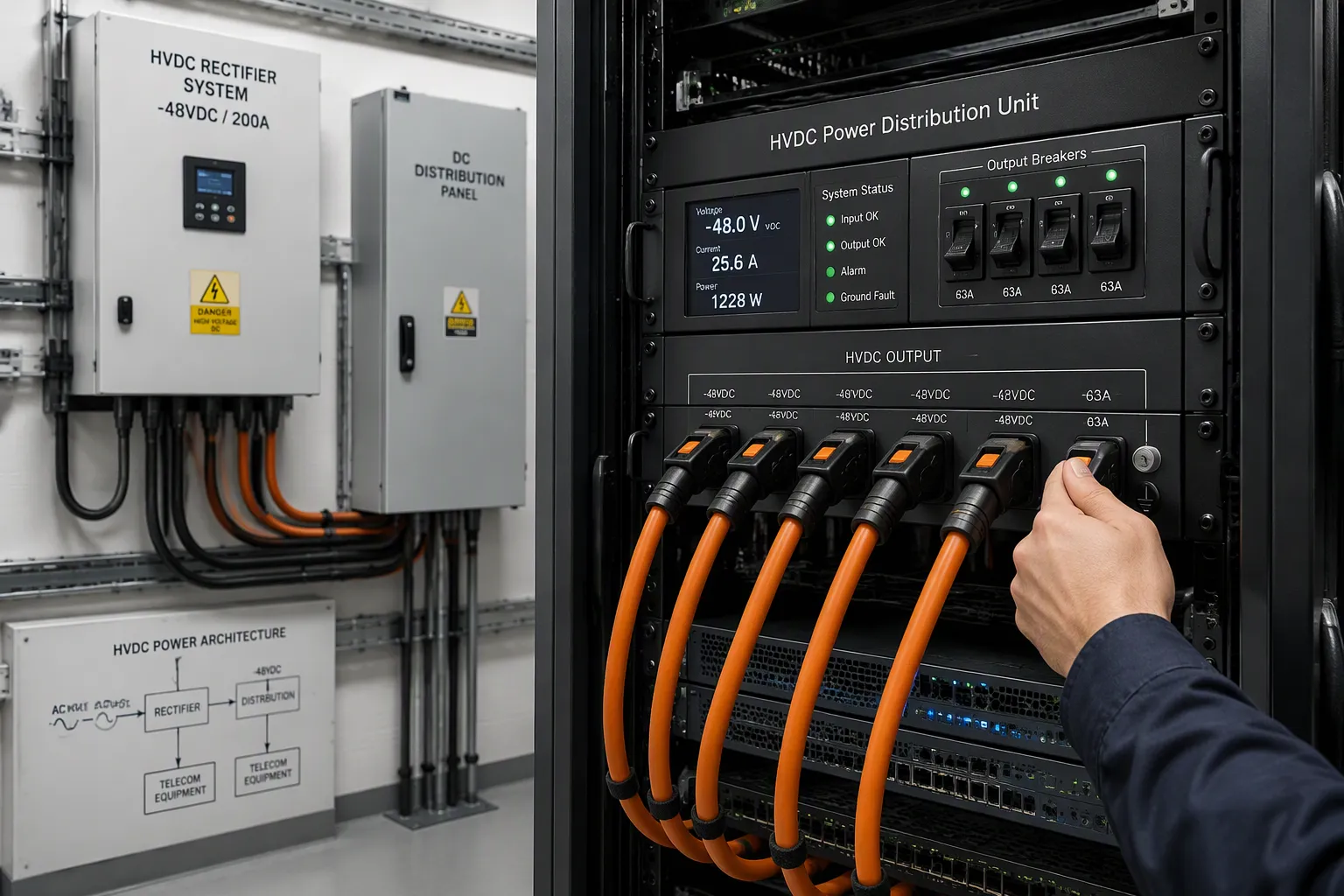
Telecom power systems can support HVDC output, and they are compatible with 240V/336V architectures when three conditions hold. First, the voltage range must cover the rectifier output and the load input window. Second, isolation must separate input from output and protect service staff. Third, protection must coordinate across rectifiers, distribution, and loads. You can treat these three conditions as the lens for every claim that follows. This article also separates technical feasibility from performance, compliance, and cost. That split lets you judge fit for your own sites. A design that works on paper may still fail your grounding, protection, or budget checks. HVDC compatibility depends on evidence, not labels.
Key Takeaways
HVDC output works with 240V/336V architectures only if three conditions pass: voltage range covers source and load, isolation separates input from output, and protection coordinates across the chain.
Always check the full voltage window on both the rectifier and load sides, not just the nominal voltage, to prevent tripping during normal swings.
Isolation and protection coordination fail more often than voltage matching, so verify these safety measures before connecting any load.
Match the feed to your site: choose 240V for edge and modular sites, 336V for dense hyperscale halls, and 800V for concentrated AI clusters.
Plan HVDC migration in stages, validating voltage tolerance, isolation, and protection at each step to keep service running.
Telecom Power Systems and HVDC Output
Rectifier and DC Plant Basics
A rectifier chain turns utility AC into regulated DC for your loads. The sequence follows a fixed path:
Utility AC enters at 230V, 400V, 415V, or 480V and passes through protective distribution stages.
AC distribution panels isolate and protect feeds to rectifiers, cooling, and HVAC.
The rectifier system converts AC to a regulated −48V DC output and shares load across modules.
A central dc bus carries that output to distribution units and branch protection.
Load equipment draws stable, low-noise −48V DC.
A battery bank sits in parallel on the bus as instant backup.
A generator restarts AC supply during long outages.
Monitoring tracks rectifier, battery, and load health.
Modern rectifier modules use high-frequency switching, hot-swappable parallel designs, and N+1 or N+N redundancy. Active power factor circuitry pushes efficiency toward 99%. This chain forms the complete -48v power system architecture that most telecom power systems still build on. Adding hvdc output means raising the rectifier output voltage and re-checking every downstream element.
Distribution Architectures Compared
Three power architecture options dominate. Centralized supply places rectifiers in one plant and feeds all loads from a single point. Distributed and isolated supply puts conversion near the load, which shortens runs and limits fault propagation. Centralized single output with intermediate bus conversion combines a central plant with local ac/dc and dc/dc conversion stages at the rack.
Each option trades installation cost against flexibility and fault tolerance. Centralized plants suit dense, uniform sites. Distributed designs fit spread-out loads. Intermediate bus designs balance both. International standardization efforts for hvdc power feeds remain underway, so no single layout is settled. Treat the choice as a site decision, not a ranking.
Hvdc in telecom changes the calculus. Higher distribution voltage cuts current for the same power delivery, which reduces conductor losses in high-voltage dc power distribution. Telecom power systems that adopt hvdc output must re-check the telecom power supply, dc power systems layout, and protection scheme against the new voltage. Plan hvdc migration as a staged path, and confirm each stage against your load map.
240V/336V Architectures Explained
Voltage Windows and Standards
Two standards anchor the Chinese market. China Telecom 240V HVDC defines the mainstream 240v hvdc feed, and China Mobile 336V HVDC sets the 336v hvdc reference. Both raise distribution voltage well above the traditional 48V plant. Higher voltage cuts current for the same power, so conductors carry less loss over long runs.
You must separate the nominal voltage from the tolerance window. The nominal value is the label on the system, such as 240V or 336V. The tolerance window is the band your rectifiers and loads must actually accept. A load rated only at the nominal point may trip during normal regulation swings. Check the full window on both the source and the load side. Confirm the figures against the current standard text, because published windows can change between revisions.
Application Fit by Site Type
Site type drives the choice between the two feeds. Dense urban sites with short cable runs often suit 240V HVDC, where the lower of the two high voltages still cuts losses against 48V. Large campuses and high-power sites lean toward 336v hvdc, which pushes more power through the same copper. Remote or legacy sites may stay on 48V until the load map justifies a change.
Match the architecture to your load profile, not to fashion. Map every load's input window, then confirm the rectifier output sits inside it with margin. Check that protection devices carry ratings for the higher dc voltage. Plan the hvdc migration in stages, and validate each stage against the standard you cite. A site that passes the voltage check may still fail on isolation or protection coordination, so treat the voltage window as the first gate, not the only one.
Compatibility Requirements for HVDC
Voltage Tolerance and Isolation
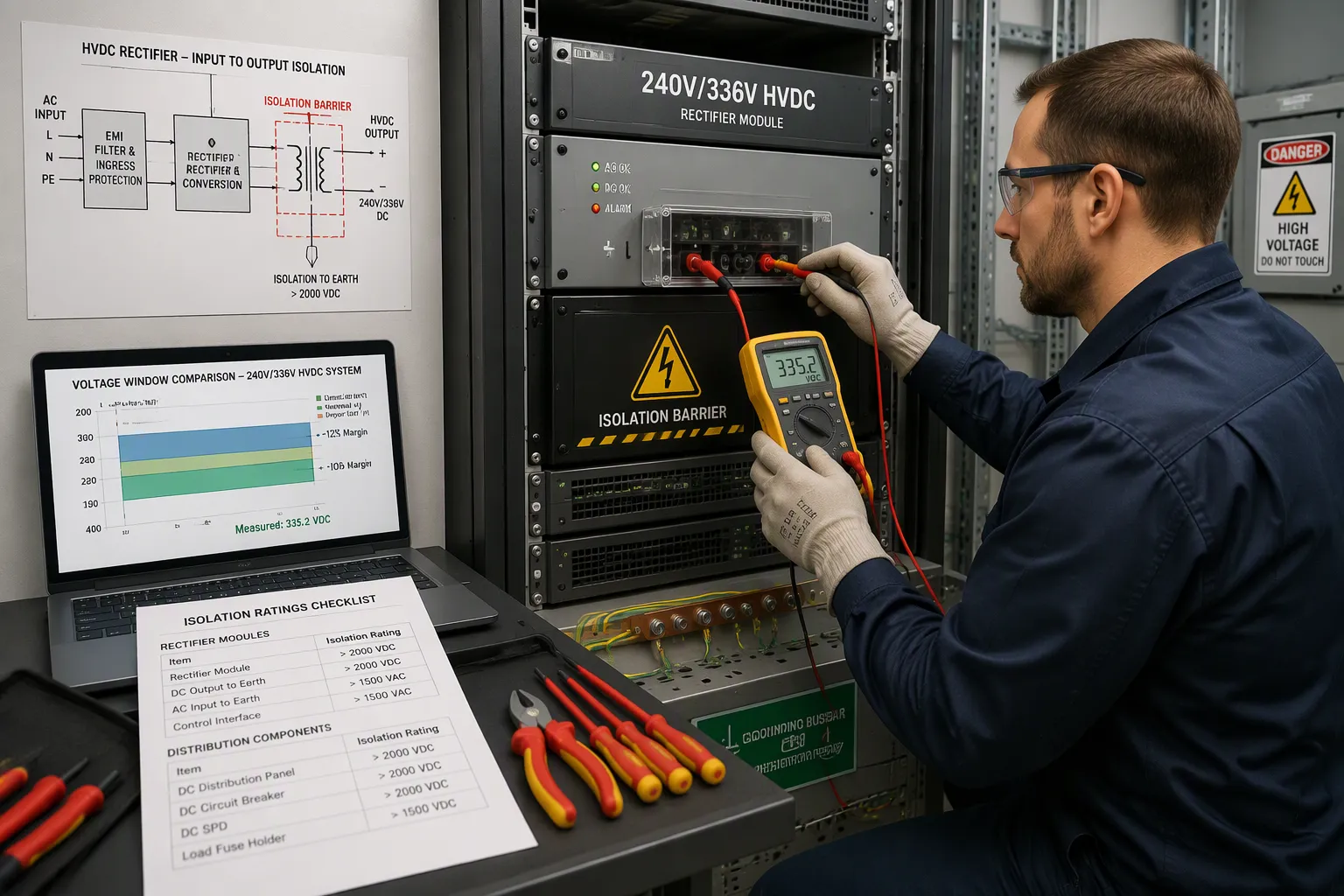
Voltage tolerance decides compatibility between your rectifiers and loads on the same hvdc feed. You must confirm that the rectifier hvdc output window sits inside every load's input window with margin at both ends. Margin means headroom at the top and bottom of the band. A load rated only at the nominal point may trip during normal regulation swings. Check the full window on the source side and the load side, then compare the two. Write the numbers down for each load, not just the nameplate nominal value. Test at both extremes of the window, not only at the center point. A single load outside the band forces a converter, a dedicated feed, or a load replacement.
Isolation comes next, and it carries equal weight. The rectifier must separate input from output, and the distribution path must protect service staff from the higher dc potential. Traditional 48V plants tolerate casual contact in many maintenance routines. A 240V or 336V feed does not offer that margin. Treat isolation as a safety requirement, not an optional feature. Ask for the isolation rating of every rectifier module and every distribution component on the path. Compatibility therefore rests on two proofs: a voltage window that overlaps with margin, and an isolation barrier rated for the full hvdc potential. Skip either proof and the design is unverified, whatever the datasheet claims.
Grounding and Protection Coordination
Grounding schemes differ sharply between the two plant families. The table below sets out the contrast.
Aspect | Traditional 48V/54V plant | 240V/336V distribution |
|---|---|---|
Typical reference | Positive terminal grounded | Grounding practice set by the cited standard |
Touch safety | Low potential, limited hazard | Higher potential, isolation critical |
Fault path | Short, low-impedance return | Requires verified return path |
Protection rating | Rated for low dc voltage | Must carry the higher dc voltage |
You must verify the grounding arrangement before you connect any load. A scheme copied from a 48V site will not transfer to a 240V or 336V hvdc distribution without review. Confirm the reference point, the bonding path, and the return conductor against the standard you cite. Document the scheme in your site drawings so the next technician follows the same reference.
Protection coordination is the second deciding factor. Breakers, fuses, and surge devices must carry ratings for the higher dc voltage, and they must trip in the right sequence. A device that clears a fault at 48V may arc or fail at 336V. Coordinate the settings across rectifiers, the dc bus, distribution branches, and loads. Set the trip thresholds so the branch device clears first and the upstream device stays closed. One weak link breaks the whole chain. Isolation and protection coordination together decide compatibility, because a voltage match alone proves nothing about safety or fault behavior. Review your dc power systems against both factors before you commit to an hvdc migration. Verify each stage in sequence, and record the evidence for the next reviewer.
800V HVDC Architecture and Migration
The 800V HVDC Architecture Shift
Data center HVDC raises distribution voltage from 48V/54V to ±400V or 800V DC. The 800v high-voltage direct current architecture targets a simple goal: convert high-voltage AC once, then distribute DC straight to the load. This 800v hvdc approach cuts conversion losses and matches on-site DC renewables such as solar and fuel cells. Industry groups position 400 Vdc distribution as an energy-conservation option, and the 800v hvdc architecture now anchors roadmaps for ai data centers.
The shift matters most where ai server power consumption climbs. A 1 mw rack exceeds what low-voltage feeds carry efficiently. Higher voltage lowers current, resistive losses, heat, and copper demand. The table below summarizes the reported benefits.
Characteristic | Reported Benefit |
|---|---|
Efficiency | Up to 5% end-to-end gain versus 54 V systems |
Copper | Up to 45% smaller cross-section versus low-voltage DC |
Conductor capacity | 85% more power through the same conductor size versus 415 VAC |
Scalability | Racks from 100 kW to over 1 MW on one infrastructure |
The chain runs from medium-voltage AC through a solid-state transformer or transformer-rectifier unit, then liquid-cooled busbars to each rack. A near-term sidecar model keeps existing upstream AC infrastructure. NVIDIA's Kyber systems adopt 800 V HVDC from 2027, and the Mt. Diablo project standardizes a ±400 VDC three-conductor system. Mature EV charging and solar supply chains accelerate adoption of protection and cooling hardware.
Planning an HVDC Migration
Treat hvdc migration as a staged path, not a single cutover. Start with your existing plants and map every load's input window. Then move loads to higher-voltage distribution in phases, validating voltage tolerance, isolation, and protection at each step. The sidecar model offers a low-risk first stage for ai data centers, because it preserves upstream AC gear while you prove the 800v dc link.
Your telecom power supply choice shapes the early stages. ESTEL's Telecom Power System accepts 90–300 Vac input and delivers 20–36 VDC at 0–150A, with natural cooling, 19-inch rack or cabinet installation, and multiple communication ports. It suits sites that need wide AC tolerance and rack-mounted DC output while you plan the jump to 800v dc. ESTEL also supplies outdoor cabinets, rectifier systems, and lithium iron phosphate batteries.
Plan the power architecture around conversion stages. Solid-state transformers and industrial-grade rectifiers replace bulky line-frequency units at the facility edge. Keep ac/dc and dc/dc conversion stages close to gpu clusters to shorten runs. For gpu power delivery, local conversion from 800v hvdc removes rack power shelves. The sst approach also lets storage connect directly to the DC bus. Weigh sst cost against copper savings before you commit. A staged hvdc migration keeps service running while high voltage dc reaches the rack.
Comparison and Best-Fit Scenarios
HVDC Versus AC Trade-Offs
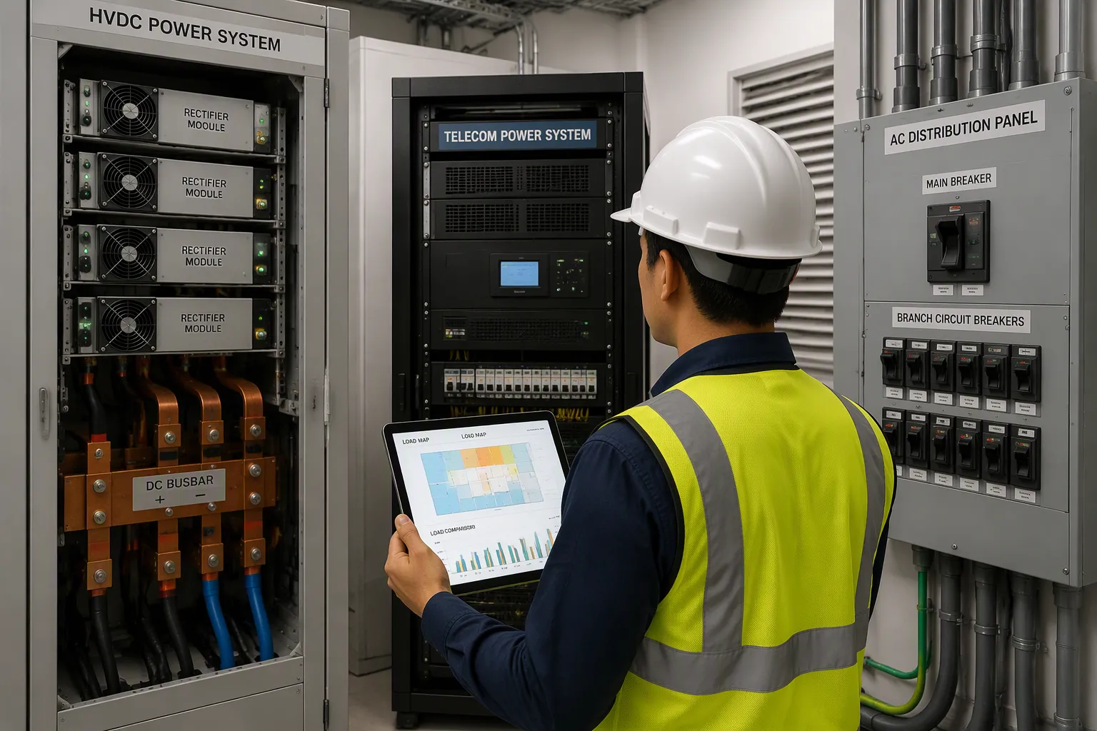
You can compare the two options on four axes. The table below sets out the trade-offs without ranking either side.
Axis | HVDC | AC |
|---|---|---|
Technical performance | Fewer conversion stages, lower conductor losses at higher voltage | Mature protection and familiar maintenance routines |
Application fit | Strong where loads sit far from the plant or density climbs | Strong where loads are small, scattered, or legacy |
Regulatory compliance | Standards still evolving for higher-voltage feeds | Well-established codes and inspection practice |
Cost | Lower cabling cost at high power, higher equipment cost at low power | Lower entry cost, higher losses over long runs |
Neither column wins everywhere. A small remote site rarely justifies the higher-voltage hardware. A dense hall with long cable runs often does. Weigh the four axes against your own load map before you choose.
Your telecom power supply choice sets the starting point. ESTEL's Telecom Power System accepts 90–300 Vac input and delivers 20–36 VDC at 0–150A. It uses natural cooling and installs on a 19-inch rack or inside a cabinet. Multiple communication ports support monitoring and integration. This unit fits sites that need wide AC input tolerance and rack-mounted DC output. ESTEL also supplies outdoor cabinets, rectifier systems, and lithium iron phosphate batteries, so you can source the full outdoor envelope from one partner.
Matching Architecture to Load
Load density decides the architecture more than any other factor. Air-cooled HVDC cabinets suit medium and low-density IDC and colocation work. A modular cabinet rated at 30 kW per module, up to 24 modules and 720 kW maximum, reaches 97% peak module efficiency. That profile fits halls with moderate rack power and steady growth.
High-density ai data centers change the picture. Conventional air cooling becomes limited above 15 kW per rack, which causes hot spots and module derating. Single-phase immersion liquid cooling answers that limit for 800v hvdc rectifiers. A sealed IP67 design runs at 0 dB module-level noise, holds component temperature spread within 4°C, and cuts system thermal management power by 43.8% against air-cooled clusters. These figures come from vendor-reported testing, so confirm them against your own thermal model.
Use the guidance below to match architecture to site:
Choose 240V for smaller high-density facilities, edge and on-premise inference, modular data centers, and micro-grids. It removes redundant AC-DC conversions and supports modular integration.
Choose 336V for hyperscale and cloud ai data centers that need dense, fully integrated distribution for large GPU clusters. It shortens the electrical path and reduces points of failure.
Choose 800V for concentrated high-density AI/GPU clusters, paired with liquid cooling.
Keep AC where loads are small, scattered, or bound to legacy inspection routines.
Plan the conversion chain early. Solid-state transformers replace bulky line-frequency units at the facility edge. Keep ac/dc and dc/dc conversion stages near the load to shorten runs. The solid-state transformer also lets storage connect straight to the DC bus. Weigh sst cost against copper savings, and check that each sst rating covers your peak load. Measure end-to-end power delivery efficiency across the whole chain, not at one converter. Good power delivery design also protects compatibility with future voltage steps. Review your dc power systems against the three conditions before you commit, and record the evidence for the next reviewer.
Telecom power systems can deliver HVDC output and work with 240V/336V architectures. That answer holds only when three conditions pass: the voltage range covers source and load, isolation separates input from output, and protection coordinates across the chain. Check all three before you commit.
Match the feed to the site. Choose 240V for edge and modular sites, 336V for dense hyperscale halls, and 800v hvdc for concentrated AI clusters. Keep AC where loads are small, scattered, or legacy.
Close every evaluation with the same checklist:
Voltage window on both sides
Isolation rating
Grounding scheme
Protection coordination
Compliance with the cited standard
Cost across the full chain
Record the evidence for each item. Compatibility then rests on proof, not assumption.
FAQ
Can a standard 48V plant simply run at a higher output voltage?
No. You must re-check every downstream element first. Rectifiers, breakers, fuses, and surge devices need ratings for the higher dc voltage. Grounding and isolation also change. A plant built for 48V will not transfer to a higher hvdc feed without review.
Which condition fails most often in practice?
Isolation and protection coordination fail more often than voltage matching. Teams check the voltage window and stop there. A load can sit inside the band and still lack a rated isolation barrier. Breakers can carry the voltage label and still trip in the wrong sequence.
Does a higher distribution voltage always save money?
No. Higher voltage cuts conductor losses over long runs. It also raises equipment cost at low power. A small, scattered site rarely justifies the hardware. Weigh cabling savings against equipment cost across the full chain before you commit.
Where does ESTEL's Telecom Power System fit?
It suits sites that need wide AC input tolerance and rack-mounted DC output. The unit accepts 90–300 Vac and delivers 20–36 VDC at 0–150A. Natural cooling and 19-inch rack or cabinet installation simplify deployment. Multiple communication ports support monitoring and integration.
Can you migrate to a higher-voltage feed without a full cutover?
Yes. Treat migration as a staged path. Map every load's input window first. Then move loads in phases and validate voltage tolerance, isolation, and protection at each step. This staged approach keeps service running while hvdc reaches more of the site.
See Also
Essential Features Of Telecom Power Supplies You Should Know
Beginner's Guide To Comprehending Telecom Power Supply Systems
Ensuring Reliable Power Supply Within Telecom Cabinets
Grid-Connected Photovoltaic Inverter And Battery System For Telecom Cabinets
Comprehending International Standards For Communication Power Supplies
CALL US DIRECTLY
86-13752765943
3A-8, SHUIWAN 1979 SQUARE (PHASE II), NO.111, TAIZI ROAD,SHUIWAN COMMUNITY, ZHAOSHANG STREET, NANSHAN DISTRICT, SHENZHEN, GUANGDONG, CHINA
