Seismic Testing of Telecom Power Systems: Connection Reliability Verification Under Sine Sweep & Random Vibration


You depend on robust connections in Telecom Power Systems to keep your network running during and after earthquakes. Seismic testing, using techniques like sine sweep and random vibration, helps you identify weak points before they can fail. This proactive approach prevents costly downtime. When you compare lab results to real-world events, you gain confidence that your equipment will perform as expected when disaster strikes.
Key Takeaways
Seismic testing helps identify weak points in Telecom Power Systems before earthquakes strike, preventing costly downtime.
Using sine sweep and random vibration tests allows you to assess how your equipment reacts to different frequencies and unpredictable shaking.
Regular inspections and maintenance of connections can prevent failures during seismic events, ensuring network reliability.
Following industry standards like GR-63-CORE ensures your equipment remains safe and functional during earthquakes.
Implementing diverse routing and redundant systems enhances connection reliability, keeping your network operational when it matters most.
Seismic Testing Overview
Purpose
Seismic testing helps you protect Telecom Power Systems from earthquake damage. You use these tests to find weak spots before they cause problems. The main goals focus on keeping your equipment working, making sure it stays safe, and preventing dangerous failures. The table below shows the key objectives of seismic testing:
Objective | Description |
|---|---|
Functional Testing | Verifying that equipment continues to function under and after seismic motion. |
Structural Integrity | Ensuring that components do not suffer from catastrophic structural failures. |
Safety | Preventing components from becoming hazards, even if they cease to function. |
By focusing on these objectives, you make sure your network stays reliable and safe during and after an earthquake.
Types of Vibration Tests
You can use different vibration tests to check the reliability of your system. Sine sweep tests help you find resonant frequencies in your equipment. These tests change the frequency and amplitude to see how your system reacts. Sine sweep tests can show you where fatigue stress might cause problems.
Random vibration tests give you a more realistic picture. They excite all frequencies within a set range, which matches real earthquake conditions better. This method helps you see how your equipment will perform when exposed to unpredictable seismic events.
Some labs also use sine-on-random testing. This combines both methods to give you a complete view of how your system handles vibration. By using these tests, you can spot weaknesses and improve your Telecom Power Systems before an earthquake strikes.
Telecom Power Systems Reliability
Connection Risks
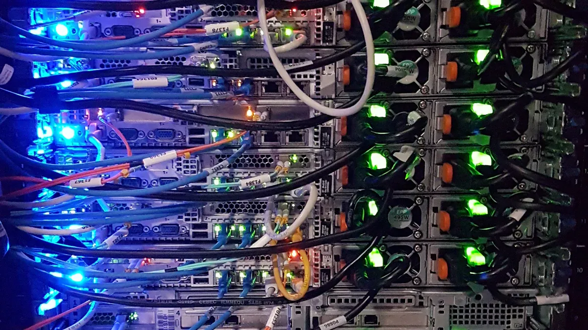
You rely on secure connections in Telecom Power Systems to keep your network stable. Loose or faulty connections can create serious risks during seismic events. When an earthquake strikes, vibrations can loosen terminals, connectors, or busbars. This movement may cause intermittent contact or even complete disconnection. You might see sparks, overheating, or even fire hazards if connections fail under stress.
Poorly maintained connections often become the weakest link. Over time, corrosion or improper tightening can make these points more vulnerable. If you do not address these issues, small faults can grow into major failures during an earthquake. Regular inspection and seismic testing help you find and fix these risks before they threaten your system.
Tip: Always check for signs of wear, discoloration, or loose hardware during routine maintenance. Early detection prevents bigger problems later.
Network Impact
Connection failures in Telecom Power Systems can disrupt your entire network. When a connection fails, power outages may occur at communication base stations. These outages can stop critical equipment from working, leading to communication breakdowns when you need them most.
You should understand how different parts of your system depend on each other. A failure in one connection can affect many components. For example:
Power outages significantly affect the functionality of these base stations, leading to potential communication failures.
A Bayesian network model evaluates the dependencies between equipment and building structures, highlighting the interconnectedness of system components during seismic events.
If you lose power at a key site, the impact can ripple through your network. Emergency services, businesses, and individuals may lose access to vital communication channels. By focusing on connection reliability, you help ensure your network stays operational when it matters most.
Sine Sweep Test
Method
You use the sine sweep test to check how your telecom power system reacts to vibrations at different frequencies. In this test, you place your equipment on a vibration table. The table moves in a controlled way, starting at a low frequency and slowly increasing to a higher frequency. The movement follows a smooth, wave-like pattern called a sine wave.
You monitor your system as the frequency changes. The goal is to see how each part responds to different vibration levels. You look for any signs of weakness, such as loose connections or abnormal noises. This method helps you find the exact frequencies that cause the most stress on your equipment.
Tip: Always secure your device under test (DUT) properly on the vibration table. This ensures accurate results and prevents accidental damage.
Resonance Detection
Resonance can cause serious problems in your telecom power system. When the vibration frequency matches the natural frequency of a component, you may see large movements or even damage. Detecting resonance is a key part of the sine sweep test.
You can spot resonance by watching for sudden increases in movement or response at certain frequencies. Here is how you detect resonance during sine sweep testing:
You sweep through a range of frequencies in a sinusoidal pattern.
You pay close attention to both high frequencies (above 1000 Hz) and low frequencies (below 1000 Hz), since resonance can occur at any point in this range.
You look for points where the device under test (DUT) shows a strong reaction. This could be extra vibration, noise, or visible movement.
If the resonance frequency does not match the operating frequency, you see little or no response. This helps you confirm which frequencies are safe.
By identifying resonance frequencies, you can strengthen weak spots and improve the reliability of your system.
Criteria
You need clear criteria to decide if your telecom power system passes the sine sweep test. These criteria focus on how well your connections handle vibrations across the frequency range. You measure two main things: return loss and cable loss (also called insertion loss).
The table below shows what you should look for:
Measurement Type | Description | Pass/Fail Criteria |
|---|---|---|
Return Loss | Measures excessive reflections due to impedance mismatches. | Entire frequency range must be below the limit line set by the carrier. |
Cable Loss (Insertion Loss) | Measures energy dissipated in connectors or cables. | Any part of the frequency sweep at or above the limit line results in a fail. |
You use these measurements to judge the health of your connections. If your system stays within the set limits, you pass the test. If not, you need to fix the problem before your equipment can be considered reliable for seismic events.
Note: Always review your test data carefully. Even a small spike above the limit line can signal a hidden issue that needs attention.
Random Vibration Test
Method
You use the random vibration test to check how your telecom power system handles unpredictable shaking. This test follows a series of important steps. Each step helps you make sure the test is accurate and reliable.
Define the objectives for your vibration test. Decide what you want to measure and set the test conditions.
Choose the right equipment. You need shakers and accelerometers that match your test needs.
Mount your specimen securely on the vibration test fixture. A loose setup can give you false results.
Set up the vibration test equipment according to the required specifications.
Take baseline measurements. These readings show the initial vibration levels before the test starts.
Apply the vibration test profile using the shaker. The profile should match the conditions you expect in real earthquakes.
Monitor the test conditions at all times. Watch for any changes or unexpected results.
Capture and analyze the vibration data. Look at how your specimen responds to the shaking.
Tip: Always double-check your mounting and equipment setup before starting the test. Small mistakes can lead to big errors in your results.
Real-World Simulation
Random vibration testing gives you a realistic view of how your telecom power system will perform during an earthquake. This method exposes your equipment to many frequencies at the same time. You do not know which frequency will cause the most stress, so this test covers all possibilities.
You see how your system reacts to unpredictable shaking, just like in a real earthquake.
The test matches the random and sudden movements found in nature.
You can check the durability and reliability of your connections under these harsh conditions.
Random vibration testing helps you find weak spots that might not show up in other tests. You get a better idea of how your system will behave when disaster strikes.
Criteria
You need clear criteria to judge if your telecom power system passes the random vibration test. These criteria focus on the performance and safety of your connections during and after the test.
Criteria Type | Description | Pass/Fail Requirement |
|---|---|---|
Functional Integrity | Equipment must operate normally during and after the test. | No loss of function or unexpected shutdowns allowed. |
Physical Condition | Connections and components must remain secure and undamaged. | No loose parts, cracks, or visible damage permitted. |
Electrical Continuity | All electrical paths must stay intact throughout the test. | No open circuits or intermittent connections detected. |
Data Consistency | Vibration data should show no abnormal spikes or sudden changes. | All readings must stay within expected ranges. |
If your system meets all these requirements, you can trust it to perform well during a real earthquake. If you find any failures, you need to fix them before your equipment goes into service.
Note: Always review your test results with care. Even a small issue can lead to bigger problems during an actual seismic event.
Verification Process
Monitoring Steps
You need a clear process to monitor and evaluate connections during seismic testing. Follow these steps to ensure your Telecom Power Systems remain reliable:
Inspect all power distribution units (PDUs) and sensors visually. Look for any signs of damage or loose connections.
Use multimeters and cable testers each month. These tools help you find damaged wires before they cause bigger problems.
Test new PDU installations with acceptance checks. Make sure every component works safely and reliably.
Run electrical tests on circuit breakers, transformers, and bus connections. Include insulation resistance checks to spot weak points.
Check the grounding system using a two-point continuity test.
Verify metering accuracy by injecting known voltages and currents.
Perform operational checks on sensors, controllers, and alarms. Confirm that all monitoring devices respond as expected.
Schedule professional inspections at least once a year. Regularly test rectifiers, batteries, and sensors to maintain system health.
Tip: Keep detailed records of each inspection and test. This helps you track trends and catch issues early.
Common Issues
During seismic testing, you may encounter several common problems:
Loose or corroded connections
Damaged wires or insulation
Faulty sensors or alarms
Inaccurate metering readings
Grounding failures
These issues can lead to unreliable performance or even system failure during an earthquake.
Solutions
You can address these problems with a proactive approach:
Tighten and clean all connections during each inspection.
Replace damaged wires and faulty components immediately.
Calibrate meters and sensors regularly to maintain accuracy.
Improve grounding by checking continuity and fixing any breaks.
Train your team to recognize early warning signs of failure.
Note: Quick action prevents small issues from turning into major failures in your Telecom Power Systems.
Standards & Best Practices
Key Standards
You need to follow strict standards when you test telecom power systems for seismic reliability. The most recognized standards include Telcordia's GR-63-CORE and ANSI Standard TI.329. These standards help you make sure your equipment stays safe and works as expected during and after an earthquake.
Telcordia's GR-63-CORE and ANSI Standard TI.329 set the benchmark for seismic equipment and supports. These standards ensure your equipment remains structurally sound and performs its intended function during simulated earthquake motions.
The table below highlights the main requirements from GR-63-CORE for seismic testing:
Requirement | Description |
|---|---|
Test Methods | You must test equipment on all three axes with defined frequency ranges. |
Response Spectrum | The test response spectrum (TRS) must exceed the required response spectrum (RRS). |
Damage Assessment | Permanent structural damage means deformation of load-bearing elements; mechanical damage includes dislocation of components. |
Functionality Verification | Your equipment must operate without component replacement or human intervention before and after testing. |
Compliance Testing | You need to ensure equipment functionality post-earthquake and identify potential installation hazards. |
Testing Guidelines
You can improve your seismic testing process by following best practices. These guidelines help you reduce risks and increase reliability:
Test equipment in high-risk seismic zones (Zones 3 and 4) using specific protocols.
Use different standards for low-risk zones (Zones 0, 1, and 2).
You should also follow these steps for every test:
Adhere to IEEE 693 and IEC 61508 standards for seismic testing and secure mounting of equipment.
Follow NFPA 70B and NFPA 70E codes to lower the risk of electrical fires and shocks.
Always match your testing approach to the seismic risk level in your area. Careful planning and strict adherence to standards help you protect your telecom power systems from earthquake damage.
By using these standards and guidelines, you make sure your connections stay reliable and your network remains operational when it matters most.
Tips for Engineers
Test Preparation
You set the stage for successful seismic testing by preparing your telecom power systems thoroughly. Start by mapping out your process and representing the plant topology. This step helps you visualize every connection and component. Define the initial residual capacity of your plant. Knowing your system’s baseline performance lets you measure changes after testing.
Next, conduct a Probabilistic Seismic Hazard Analysis. This analysis helps you understand the types and strengths of earthquakes your site may face. Evaluate possible seismic damage scenarios. You can then plan for the most likely risks and address weak points before testing begins.
Map your process and plant topology.
Define the initial residual capacity of your plant.
Perform a Probabilistic Seismic Hazard Analysis.
Evaluate seismic damage scenarios.
Tip: Document every step. Clear records help you track improvements and spot recurring issues.
Reliable Connections
You can boost the reliability of your telecom power system connections by using proven design strategies. Diverse path routing creates multiple physical routes for network connections. This approach reduces the risk of a single point of failure. Redundant power systems, such as backup generators and uninterruptible power supplies (UPS), keep your equipment running during outages.
Equipment redundancy ensures that backup devices take over if primary hardware fails. Geographic redundancy spreads your infrastructure across different locations, helping your network survive localized disasters. Network monitoring and automation tools let you spot problems early and switch to backup systems automatically.
Use diverse path routing for network connections.
Integrate redundant power systems like generators and UPS.
Deploy backup network equipment for hardware failures.
Spread infrastructure across multiple locations.
Implement monitoring and automation for quick failover.
You can also apply intentional islanding to maintain power supply after an earthquake. Monte Carlo simulations help you model uncertainties in energy generation and failures. Local distributed energy resources, such as gas turbines and solar panels, supply critical loads when the main grid is down.
Note: Combining these strategies gives your telecom power systems the best chance to stay operational during and after seismic events.
Seismic testing, including sine sweep and random vibration, helps you verify the reliability of Telecom Power Systems connections. You can estimate fatigue life and spot weak solder joints using vibration tests:
Test Type | Focus | Frequency Range | Key Findings |
|---|---|---|---|
Random Vibration Test | Fatigue life of solder joints | 10 Hz to 2000 Hz | Remaining useful life estimation |
Recent case studies show seismic isolation can reduce failure probability by 27.8% and extend structure resilience. Long-term data collection confirms that testing does not harm network quality. By following standards and best practices, you strengthen your system’s performance during earthquakes.
FAQ
What is the main difference between sine sweep and random vibration tests?
You use sine sweep tests to find specific frequencies that cause stress in your equipment. Random vibration tests expose your system to many frequencies at once. This method better simulates real earthquake conditions.
How often should you perform seismic testing on telecom power systems?
You should test new installations before use. Schedule regular tests every one to three years, depending on your risk zone and equipment age. Frequent testing helps you catch problems early.
Can seismic testing damage your equipment?
Seismic testing uses controlled vibrations. If you follow proper procedures and secure your equipment, you avoid damage. Always inspect your system before and after each test to ensure safety.
Why do you need to follow standards like GR-63-CORE?
Standards like GR-63-CORE give you clear rules for testing. They help you make sure your equipment stays safe and works during earthquakes. Following standards also helps you meet legal and industry requirements.
See Also
Ensuring Consistent Power Supply for Telecom Equipment
How ESTEL Maintains Ideal Voltage in Telecom Systems
Essential Insights on Power Supply Features for Telecom
CALL US DIRECTLY
86-13752765943
3A-8, SHUIWAN 1979 SQUARE (PHASE II), NO.111, TAIZI ROAD,SHUIWAN COMMUNITY, ZHAOSHANG STREET, NANSHAN DISTRICT, SHENZHEN, GUANGDONG, CHINA