On-Site Troubleshooting for Telecom Cabinet Communication Power Systems: Tool Checklist & Four-Step Localization

Minimize downtime and ensure reliability when you troubleshoot telecom power systems on site. Nearly 29% of telecom data center outages result from power failures, with power distribution issues contributing another 11%. A systematic approach with a clear checklist and four-step process improves safety, efficiency, and accuracy. Real-time monitoring and organized workflows reduce repair times by over 40%, preventing delays and costly emergency visits. You safeguard network performance and avoid unnecessary risks by following proven troubleshooting methods.
Key Takeaways
Prepare a complete tool kit including a multimeter, protocol analyzer, insulation tester, and safety gear to troubleshoot telecom power systems efficiently and safely.
Follow a four-step troubleshooting process: start with visual inspection, verify power, isolate faulty components, and validate the entire system to reduce downtime and improve reliability.
Use personal protective equipment (PPE) and follow safety procedures to protect yourself from electrical hazards during maintenance.
Keep accurate documentation of electrical metrics, configurations, and maintenance logs to track issues, comply with standards, and improve emergency response.
Adopt regular maintenance routines, use checklists, and train your team to prevent common faults, speed repairs, and extend equipment life.
Tool Checklist
Essential Tools
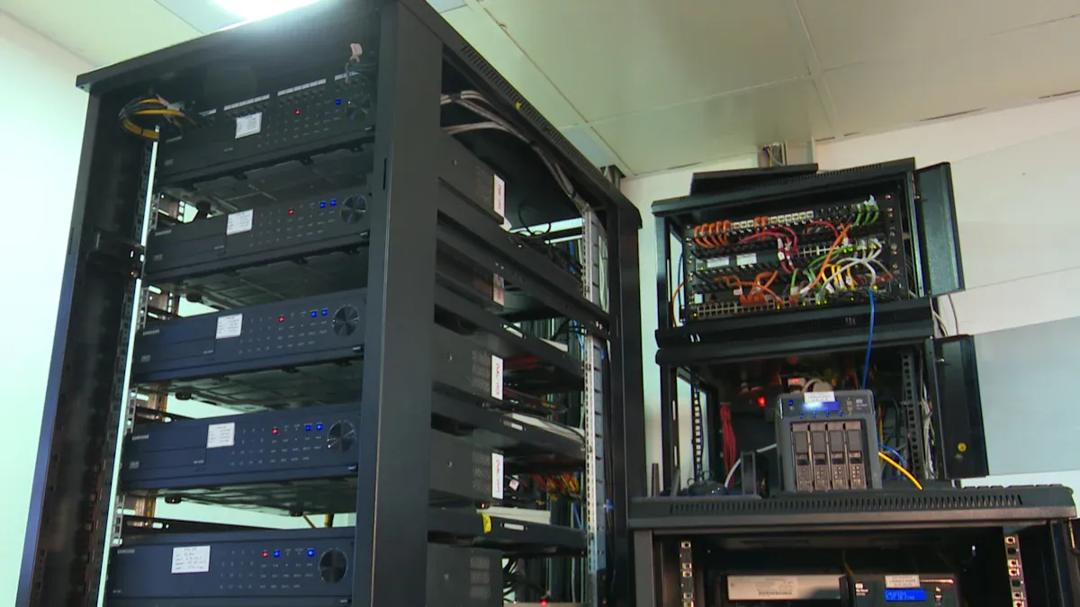
You need the right tools to diagnose and repair telecom cabinet issues efficiently. A well-prepared kit ensures you can address faults quickly and avoid unnecessary delays. Here are the most commonly used tools for on-site troubleshooting:
Multimeter – Measures voltage, current, and continuity. Use it to verify wiring and check RS485 line polarity.
Protocol Analyzer – Monitors RS485 bus data traffic and helps identify error frames or intermittent communication problems.
RS485-to-USB Converter – Connects RS485 devices to your computer for detailed protocol analysis.
Insulation Tester – Checks cable insulation integrity to prevent short circuits.
Cable Tester – Identifies wiring faults and verifies cable connections.
Screwdrivers, Pliers, Wire Strippers – Essential for opening panels, tightening connections, and preparing wires.
Thermal Camera – Detects overheating components and helps prevent equipment failure.
A comprehensive checklist streamlines your workflow. It supports preventive maintenance, reduces downtime, and adapts to evolving network technology. Missing essential tools increases failure rates, extends downtime, and raises maintenance costs.
Safety Equipment
Your safety comes first during troubleshooting. Always use personal protective equipment (PPE) that meets industry standards. Required items include:
Protective clothing that resists arcing and combustion
Hard hats with proper voltage ratings
Electrician’s gloves, tested and rated for electrical work
Eye and face protection against debris and chemical splashes
Fall arrest systems for elevated work, including harnesses and lanyards
Tip: Regularly inspect and maintain your PPE. Proper training ensures you use equipment correctly and reduces workplace injuries.
PPE acts as a barrier against hazards like cuts, impacts, and electrical shocks. Consistent use of safety gear lowers injury rates and supports a safe work environment.
Documentation Materials
Accurate documentation is vital for effective troubleshooting and long-term reliability. Use digital tools to automate data collection and performance analysis. Keep records of:
Electrical metrics: voltage, current, power, and energy consumption
Device addresses and integration steps
Alarm and error codes
Checklists and maintenance logs help you track service history, spot trends, and comply with regulations. Thorough documentation reduces downtime, extends equipment life, and improves emergency readiness.
Troubleshooting Steps for Telecom Power Systems
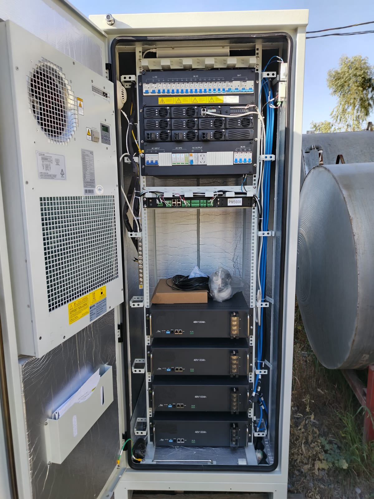
A structured troubleshooting process helps you quickly localize faults and restore service in telecom power systems. By following these four steps—visual inspection, power verification, component isolation, and system validation—you reduce downtime and improve reliability. The following guide provides actionable instructions and best practices for each stage.
Visual Inspection
Start with a thorough visual inspection. This step often reveals the root cause of many issues before you use any tools.
Check for obvious signs of damage, such as burnt components, melted insulation, or loose wires.
Look for corrosion on terminals, connectors, and grounding points.
Inspect for dust buildup, blocked vents, or foreign objects that could cause overheating.
Verify that all modules and cables are securely seated and labeled.
Tip: Organized cabling and clear labeling reduce human error and speed up troubleshooting. Structured cabling also improves cooling and minimizes accidental disconnections.
Regular visual checks help you spot problems early and prevent escalation. You also ensure compliance with safety standards and manufacturer guidelines.
Power Verification
After the visual check, verify power input and output. This step confirms that the telecom power systems receive and deliver the correct voltage and current.
Use a multimeter to measure input voltage at the main terminals.
Check output voltage and current at distribution points.
Confirm polarity and continuity on all critical lines.
Inspect battery backup status and verify charge levels.
Review alarm indicators and error codes on the system display.
A structured approach to power verification reduces mean time to repair (MTTR) and manual triage time. The table below shows how a systematic process improves key metrics:
Metric Description | Improvement/Reduction |
|---|---|
Mean Time to Repair (MTTR) | |
Manual triage time via automated categorization | Reduced by 58% |
Response time reduction from real-time drone feeds | Reduced by 30 minutes |
Maintenance response time via remote monitoring | Improved by 40% |
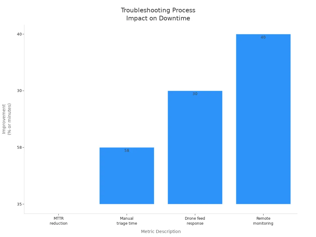
Note: Remote monitoring and automated alerts enable early fault detection and faster repairs. These tools help you identify issues before they impact network performance.
Component Isolation
If you detect abnormal readings or persistent faults, isolate the faulty component. This step prevents further damage and allows targeted repairs.
Remove and test modular, hot-swappable rectifier units one at a time.
Use real-time monitoring to check voltage, temperature, and battery health for each module.
Employ redundant power configurations (N+1 or N+2) to maintain service during isolation.
Test circuit breakers and fuses, replacing any that fail.
Inspect surge protection devices for signs of recent voltage spikes.
Follow lockout/tagout procedures to ensure safety during component removal.
Tip: Preventive maintenance, including regular cleaning and firmware updates, helps you detect faults early and extend equipment life.
Component isolation in telecom power systems minimizes downtime and supports continuous operation. Staff training and readiness drills further improve your response to faults.
System Validation
After repairs or replacements, validate the entire system to ensure safe and reliable operation. This step confirms that telecom power systems meet performance and safety standards.
Inspect power distribution units (PDUs) for wear and replace compromised parts immediately.
Clean cooling fans, vents, and filters to prevent overheating.
Test rectifiers, circuit breakers, and fuses under load conditions.
Monitor voltage, current, and temperature using remote tools.
Verify grounding by checking continuity and inspecting for corrosion.
Integrate battery backup and synchronize with communication equipment.
Configure system settings and enable monitoring features.
The table below summarizes best practices for system validation:
Best Practice Aspect | Description |
|---|---|
Prompt Replacement of Worn Components | Inspect PDUs regularly for wear and replace compromised parts immediately. Use manufacturer-approved components. |
Regular Inspections and Cleaning | Schedule routine inspections and cleanings to remove dust and debris. Use HEPA-filter vacuums and soft cloths. |
Testing Rectifiers and Circuit Protection | Test rectifiers and circuit breakers regularly and keep spares ready. |
Monitoring Load Balancing and Power Usage | Use remote monitoring tools to track voltage, current, and load distribution. Set alerts for abnormal readings. |
Grounding Verification | Ensure proper grounding by securely connecting wires and verifying continuity with a multimeter. |
Post-Repair Testing and Validation | Perform comprehensive testing under load conditions and confirm integration with communication equipment. |
Safety Precautions | Always power down equipment before maintenance and use PPE. Isolate power sources during repairs and validation. |
You can also use these key metrics to confirm successful validation:
Metric Category | Metric Name | Threshold/Condition |
|---|---|---|
Amplitude Stability | Amplitude Error (AE) | |
Amplitude Fluctuation Rate (AFR) | ≤ 1% | |
Frequency Stability | Frequency Error (FE) | ≤ 0.5% |
Frequency Fluctuation Rate (FFR) | ≤ 0.25% | |
Sinusoidal Purity | Total Harmonic Distortion (THD) | ≤ 1% |
Efficiency | Inverter Efficiency (η) | ≥ 95% |
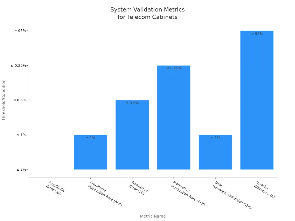
Note: Always perform post-repair testing under load and confirm all system settings. Proper validation ensures long-term reliability and compliance with industry standards.
Common Issues & Solutions
Frequent Faults
You often encounter several recurring problems when working with telecom power systems. Addressing these issues quickly helps you maintain system reliability and prevent costly downtime.
Loose wires and poor grounding frequently disrupt cabinet operations. You should check all connections and grounding points during every inspection.
Power and control wire faults can appear due to wear or improper installation. Regularly tightening and securing wires reduces these failures.
Dust and water ingress threaten sensitive equipment. You need to inspect seals and filters to keep out environmental hazards.
Cooling system malfunctions, such as clogged fans or dirty filters, cause overheating. Cleaning and replacing filters ensures stable temperatures.
Battery faults and aging components lead to unexpected shutdowns. Timely replacement of batteries and worn parts prevents larger failures.
Surge protector failures and structural weaknesses often go unnoticed. Professional inspections help you detect these hidden risks.
Temperature spikes and humidity fluctuations damage internal components. Monitoring environmental conditions inside the cabinet protects your equipment.
Unauthorized access, vandalism, or theft—especially of copper wire and batteries—pose security risks. You should secure cabinets and monitor for tampering.
Tip: Schedule routine checks for dust, water, and smoke. Early detection of environmental hazards keeps your telecom power systems running smoothly.
Quick Fixes
You can resolve many common faults with targeted actions that restore service and minimize downtime.
Use a primary power shutdown (LLVD) to disconnect all power for full maintenance or emergencies. This approach allows you to safely inspect and repair the entire system.
Apply a secondary power shutdown (BLVD) to isolate specific equipment. This method supports partial maintenance and backup switching without affecting critical loads.
Combine LLVD and BLVD strategies for flexible power management. You gain the ability to tailor shutdowns to operational needs.
Implement advanced replacement programs. Swapping faulty units with working ones reduces repair time and keeps your network online.
Retrofit cabinets to block water or pest ingress. Simple modifications extend equipment life and reduce repeat failures.
Use diagnostic tools for precise fault detection. Comprehensive hardware testing verifies repairs before you return equipment to service.
Replace aging components proactively. This step lowers the risk of unexpected failures and reduces the need for emergency visits.
Re-certify recovered equipment when possible. Repair avoidance strategies help you control costs and maintain reliability.
Note: Intelligent control and redundancy in power management systems help you maintain stability and reduce downtime during repairs.
Pro Tips
Workflow Efficiency
You can streamline troubleshooting in telecom power systems by adopting proven workflow strategies. Start by using checklists for every inspection. Checklists help you avoid missed steps and ensure thorough maintenance. Keep your essential tools—like screwdrivers, pliers, and multimeters—organized and ready for quick access. Establish a regular maintenance plan that includes monthly inspections and quarterly cleanings. This routine prevents unexpected failures and extends equipment life.
Train your team on cabinet care and troubleshooting techniques. Well-trained staff respond faster and make fewer errors. Maintain detailed records and logs for each cabinet. These records help you track recurring problems and plan future upgrades. Pre-install accessories such as rack-level PDUs before shipping cabinets to reduce onsite labor. Use digital tools, like DCIM software, to manage assets and documentation efficiently.
Tip: Design your telecom room with maintenance in mind. Use cooling strategies such as Hot Aisle or Cold Aisle Containment to improve operational conditions and reduce downtime.
Avoiding Mistakes
Common mistakes can lead to costly outages and equipment damage. Skipping routine inspections often results in missed signs of wear, corrosion, or loose connections. Always use a checklist to guide your inspections and ensure nothing gets overlooked. Poor cleaning habits allow dust and debris to block airflow, causing overheating. Clean cabinets regularly with anti-static brushes and avoid liquids near electrical parts.
Ignoring alerts from sensors or monitoring systems can result in fires or equipment failures. Respond promptly to all alerts to prevent disasters. Incomplete documentation makes it hard to track maintenance and comply with regulations. Standardize your data collection and use automated logging tools for accuracy. Faulty electrical connections, such as loose or damaged wiring, cause overheating and failures. Inspect, tighten, and replace connections as needed.
Note: Schedule calibration checks and firmware updates to keep sensors accurate and systems secure. Good documentation practices and routine maintenance keep telecom power systems reliable and efficient.
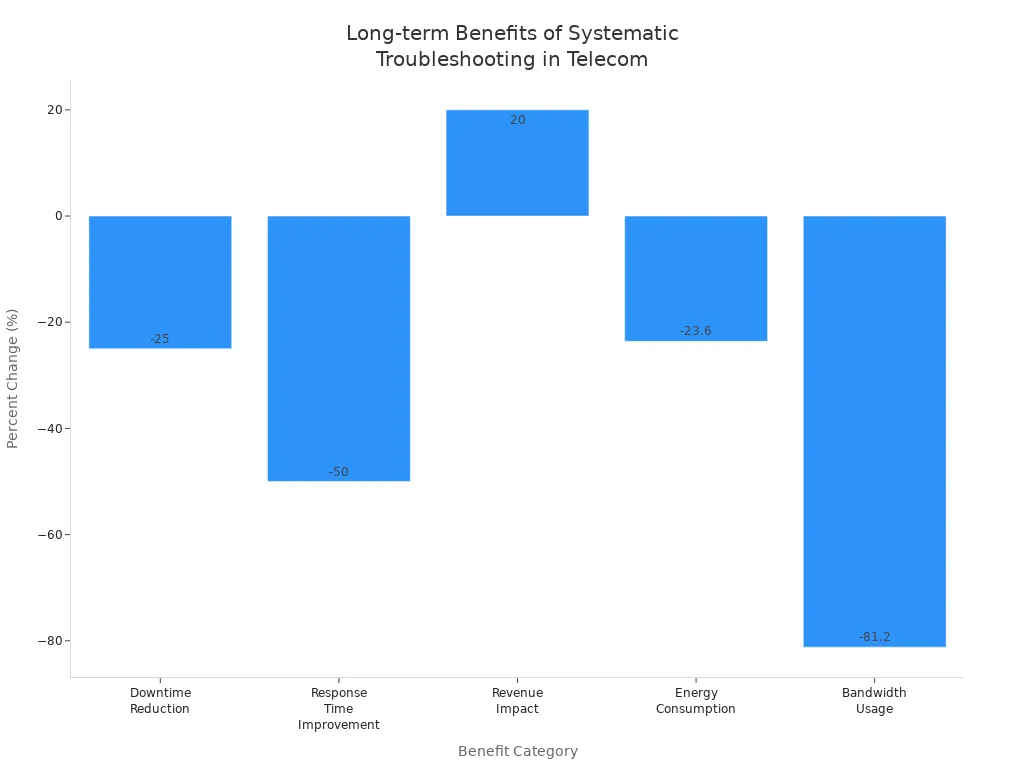
You gain faster, more accurate troubleshooting and higher system uptime when you use a detailed tool checklist and follow the four-step localization process for telecom power systems. Organizations that adopt these methods see measurable improvements:
Benefit Category | Description | Measured Impact / Metric |
|---|---|---|
Downtime Reduction | Faster response and fewer interruptions | |
Response Time | Enhanced operational efficiency | Response times improved by 50% |
Revenue Impact | Operational improvements lead to financial gains | Revenue increased by 20% |
Energy Consumption | Optimized energy management | Energy consumption reduced by 23.6% |
Bandwidth Usage | Efficient data transmission | Bandwidth usage decreased by 81.2% |
Equipment Uptime | Reliable multi-device operation | Increased uptime and reliability |
Share your own tips or experiences to help others improve their telecom power systems. Stay committed to continuous improvement and always prioritize safety.
FAQ
What should you do first when troubleshooting a telecom cabinet?
Start with a visual inspection. Look for loose wires, burnt components, or signs of water damage. Organized cabling and clear labeling help you spot issues quickly.
Which tool is most important for diagnosing power faults?
You need a multimeter. It measures voltage, current, and continuity. This tool helps you verify power input and output, ensuring safe and accurate troubleshooting.
How often should you inspect safety equipment?
Check your PPE before every site visit. Inspect gloves, helmets, and clothing for damage. Replace any worn or expired items immediately to maintain safety standards.
Why is documentation critical during maintenance?
Accurate records help you track repairs, spot recurring problems, and comply with regulations. Use digital logs to automate data collection and improve reliability.
Can you use remote monitoring to reduce downtime?
Yes. Remote monitoring detects faults early and sends alerts. You respond faster, prevent major failures, and keep your telecom power systems running efficiently. 🚦
See Also
Steps To Guarantee Consistent Power For Telecom Cabinets
Choosing And Mounting Telecom Cabinets On Poles Safely
Best Practices For Effective Outdoor Telecom Cabinet Monitoring
ESTEL’s Comprehensive Overview Of Telecom Cabinet Specifications
Complete Instructions For Wiring And Cable Choices In Telecom
CALL US DIRECTLY
86-13752765943
3A-8, SHUIWAN 1979 SQUARE (PHASE II), NO.111, TAIZI ROAD,SHUIWAN COMMUNITY, ZHAOSHANG STREET, NANSHAN DISTRICT, SHENZHEN, GUANGDONG, CHINA

