How to Implement Multiple Lightning and Surge Protection for Telecom Rectifier Systems

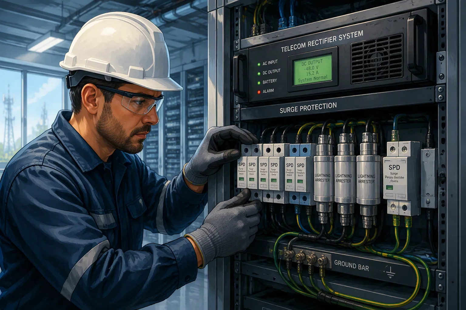
Multiple protection for telecom rectifier systems is a coordinated protection chain. Primary AC input SPDs, secondary DC output and communication port defenses, correct grounding and bonding, and proper SPD coordination all divert surge energy before it reaches sensitive rectifier electronics.
You build layered protection from four parts: AC input, DC output, communication and signal ports, and grounding. SPDs alone are not lightning protection. Internal surge protection must pair with external measures. Surges enter through all four paths, so each one needs its own defense.
This post gives you actionable surge protection guidance on selection, placement, coordination, testing, and compliance. ESTEL's Telecom Rectifier System and SPD-ready cabinet designs support this approach.
Key Takeaways
Surges can enter through AC power, DC output, communication lines, and ground paths. Protect all four paths.
Install primary AC surge protection at the service entrance. Add secondary DC and communication port protection near equipment.
Keep at least 10 meters of cable between protection stages. Use a decoupling inductor if space is tight.
Ground and bond all equipment at a single point. Aim for 10 ohms or less ground resistance.
Check surge protection devices and grounding regularly. Replace failed devices and keep spares on hand.
Mapping Surges in Telecom Rectifier Systems
Surge Entry Points and Protection Zones
Surges reach a rectifier site through four paths. The AC service entrance carries the largest energy from lightning strikes on the utility line. DC output runs pick up coupled energy along cable routes. Communication and signal lines bring in lightning-induced surges from outside plant cabling. Ground paths complete the circuit and can raise local potential during a strike.
You map these paths to three protection zones. IEEE Recommended Practice C62.41.2 describes this cascaded architecture:
First layer — service entrance: handles the largest surge energies from direct lightning exposure.
Second layer — distribution panels and motor control centers: reduces residual voltage to levels acceptable to equipment.
Third layer — point of use: provides final clamping for sensitive electronics.
The same practice applies to telecom dc systems, where central office equipment and subscriber line circuits need protection. Short lead lengths and proper grounding matter as much as device selection, because lead impedance adds to effective let-through voltage.
Withstand Levels and Standard Basis
Set withstand levels from a standard basis, not from guesswork. Size each stage for the energy it must absorb. IEEE Std C62.41 guides service entrance selection:
8.6.3 Service entrance surge protection — Facilities housing electronic load equipment of any type should have service entrances equipped with effective lightning protection in the form of listed Category "C" SPDs, as specified in IEEE Std C62.41. Care should be taken to assure that the method used for the installation of surge protective device equipment does not cause a degradation of its current-diverting and voltage-clamping abilities.
Equipment with both AC power and data cabling needs surge protection devices on both paths:
8.6.6 Data/communication/telecommunication systems surge suppression — Electronic equipment containing both ac power and data cabling should also be properly protected via SPDs on both the ac power and data cables.
Remember one limit. Surge protection devices alone do not stop lightning. Internal dc surge protection must pair with external measures — air terminals, down conductors, and grounding — to divert transient overvoltages before they enter the cabinet.
Protecting Telecom Rectifier Systems at AC and DC
Primary AC Input SPD Selection
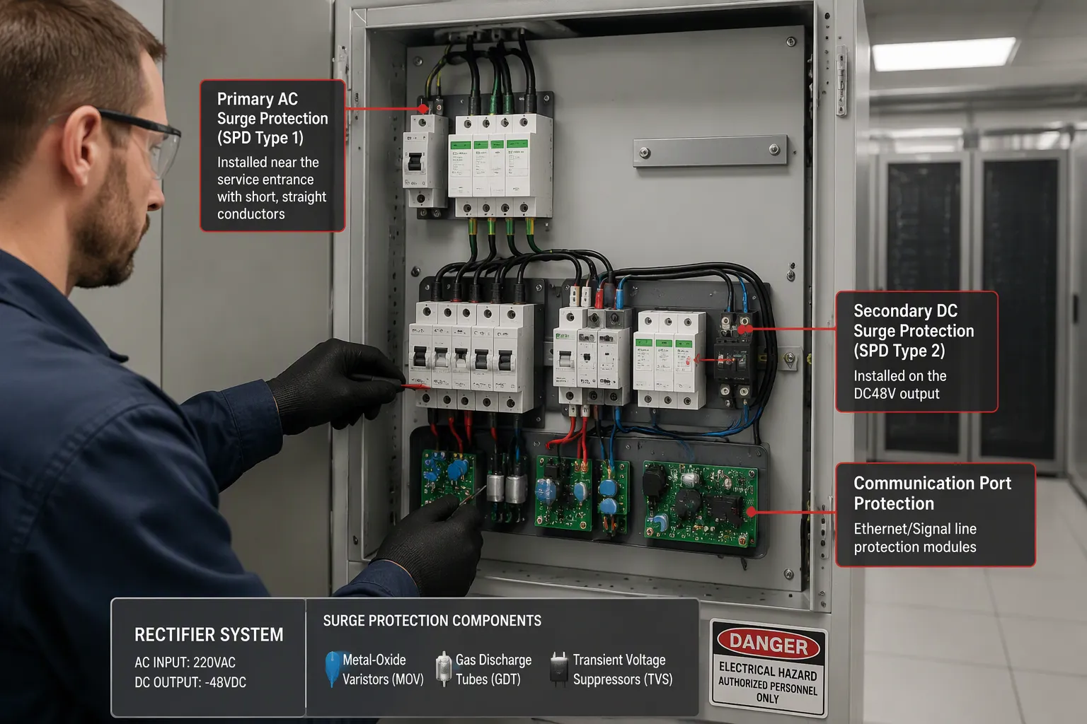
Select primary AC surge protection devices by the relevant standard, then install them as far upstream as possible. The service entrance is the correct location. This placement lets the first stage handle the bulk of surge energy before it travels deeper into the building.
Match the SPD type to your grounding system. A device designed for a solidly grounded wye service will not perform correctly on a high-impedance grounded system. Check the manufacturer's listing against your site configuration before you order.
Avoid common NEC Code violations during installation. Route SPD conductors as short and straight as possible. Add overcurrent protection where the code requires it. Improper conductor routing adds impedance and raises let-through voltage. Missing overcurrent protection creates a fire risk during a large surge event.
These steps form the foundation of surge protection for power supplies in any telecom rectifier system. A well-chosen primary stage protects the entire downstream chain.
Secondary DC and Communication Protection
Add secondary dc surge protection devices at the DC48V output and on every communication and signal port. These devices clamp the residual voltage that the primary stage lets through. This second layer is essential for dc surge protection in telecom sites with long cable runs.
Different suppression technologies serve different roles. Metal-oxide varistors handle high-energy transients and suit DC output paths. Gas discharge tubes absorb bulk surge energy on communication lines. Transient voltage suppressors clamp residual voltage tightly and respond quickly. You often combine these technologies for the best result.
Protection Area | Application | Recommended Technology | Rationale |
|---|---|---|---|
DC output | High-energy DC path | DC-rated MOV | Handles high-voltage, high-energy lightning surges |
Communication port | Telecom line interface | GDT plus low-capacitance TVS | GDT absorbs bulk energy; TVS clamps residual |
Communication port | Ethernet PoE | GDT, series inductor, low-cap TVS | GDT diverts surges; TVS protects the PHY |
Choose gas discharge tubes when line loading must stay minimal and surge current capability must be maximized. Choose transient voltage suppressors when clamping voltage must be tightly controlled and response time must be fastest. For communication ports exposed to high surge energy, combine a primary gas discharge tube stage with a secondary low-capacitance TVS stage.
ESTEL's Telecom Rectifier System makes this layered approach straightforward. The DC48V output, modular 2U/3U/6U rack-mount design, and 19-inch rack compatibility let you integrate upstream AC surge protection devices and downstream dc surge protection devices installed near equipment with minimal effort. Grounding protection through a copper bar simplifies bonding. These purpose-built dc surge protection features support reliable operation in dc-powered telecom environments.
Coordinating SPDs, Grounding, and Bonding
Energy Distribution Between Stages
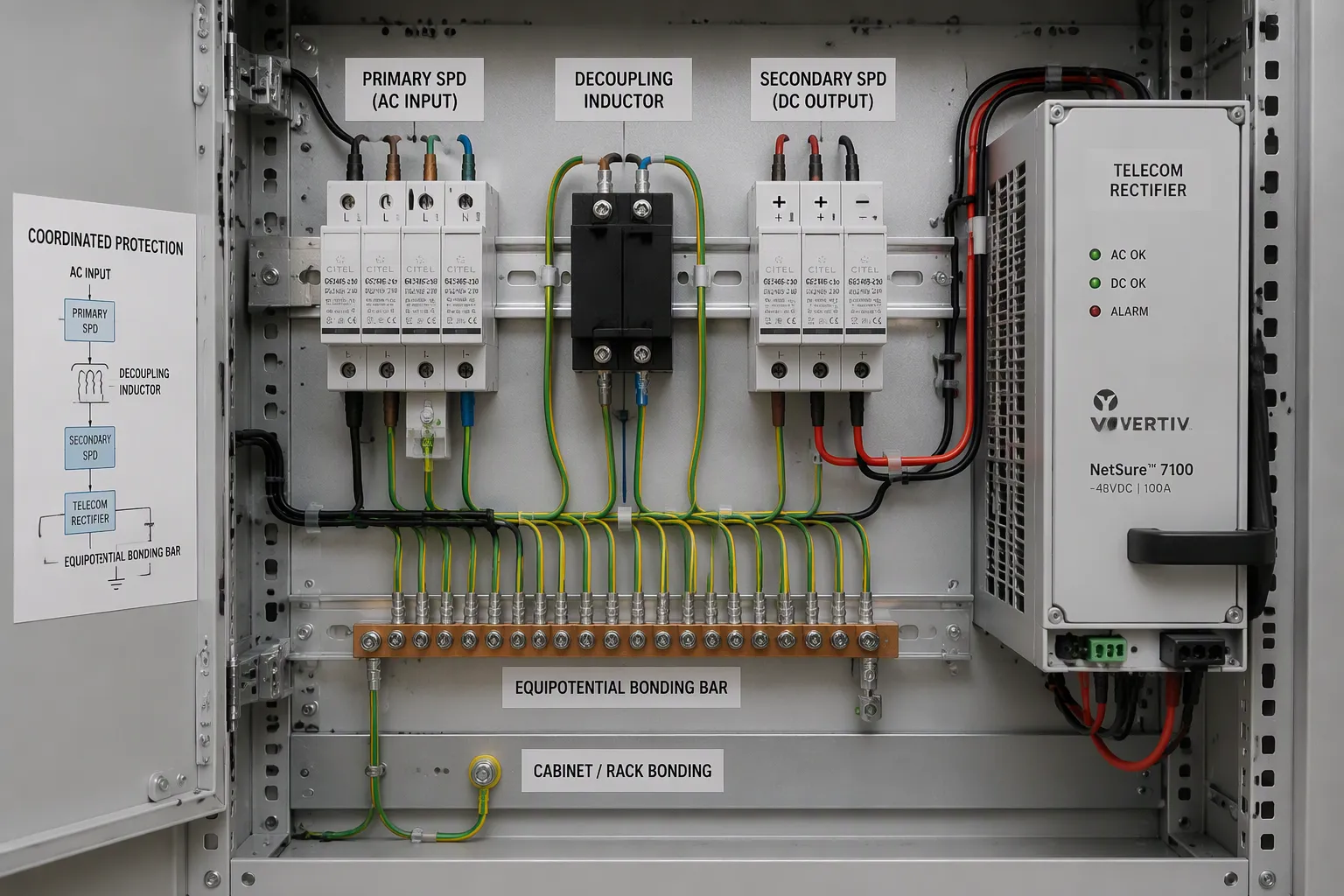
A coordinated chain shares energy by design. The primary SPD absorbs the bulk of the surge energy at the service entrance. The secondary SPD clamps the residual let-through voltage near the equipment. Each stage must hand off energy correctly, or the second stage takes a hit it cannot survive.
You control this handoff in three ways. The table below shows the minimum requirements for each method.
Coordination Method | Minimum Requirement |
|---|---|
Cable length between stages | At least 10 m |
Decoupling inductor | 15–30 μH (depending on SPD characteristics) |
Combined devices | Per manufacturer specification |
Cable length alone provides natural impedance between stages. A run of at least 10 m lets the first stage trigger before the second stage sees the full wavefront. Where space is tight, a decoupling inductor of 15–30 μH substitutes for that distance. Combined Type 1+2 SPDs integrate primary and secondary protection in one unit. They need no decoupling inductor and no separation distance, which suits compact or space-limited installations.
This staged arrangement delivers true coordinated protection. It also keeps your dc surge protection devices within their rated energy window.
Grounding and Bonding Essentials
Grounding and bonding practices decide whether your SPDs work at all. Use single-point bonding. Route ground conductors short and straight. Bond the cabinet, rack, and ground bar together at one equipotential point.
Ground resistance targets depend on the application.
Application | Recommended Ground Resistance |
|---|---|
Telecom towers and equipment (general) | ≤ 10 ohms |
Sensitive telecom equipment (ideal) | ≤ 5 ohms |
Poor grounding is a common installation mistake. It undermines SPD performance and can violate NEC Code. Watch for these faults:
Weak or high-impedance grounding paths. Impedance, not just resistance, matters during fast surges.
Long, looped, or high-inductance conductor routing. Low-frequency testing can look fine while fast transients fail.
Poorly bonded connections on painted surfaces, loose lugs, or corroded points.
Incorrect PE terminal connection, which blocks controlled surge diversion.
Missing bonding jumpers where the design requires them.
Deviating from manufacturer grounding instructions or the electrical code.
Wiring errors also defeat protection. Reversing line and neutral terminals is a classic fault. Treating PE and N as interchangeable is another. Using an AC SPD in a DC circuit, or installing a DC SPD with wrong polarity, damages the device. Omitting the neutral-to-earth module where required leaves a gap. Applying a three-phase diagram to a single-phase panel miswires the whole stage.
Every one of these errors raises impedance or breaks the diversion path. Check each termination against the manufacturer's instructions before you energize the system.
Testing, Cost, and Compliance for Telecom Rectifier Systems
Test and Maintenance Routines
A protection chain only works when you verify it. Build a routine that checks every stage on a fixed schedule. Start with the status indicators on each surge protection device. Most units show a clear window or LED that changes state at end of life. Replace any cartridge that shows the failed state, and log the date.
Measure ground resistance at each bonded point during the same visit. Compare the reading against your site target and record any upward drift. Loose lugs and corrosion raise impedance over time, and a slow rise often signals a failing connection. Schedule a full inspection after any known lightning event near the site. A nearby strike can exhaust a cartridge without tripping a breaker.
Keep spare cartridges on hand for every model you install. A failed device left in place offers no protection, and a long wait for parts leaves the site exposed. Train your technicians to read the indicators and to torque terminations to the manufacturer's specification.
Balancing Cost and Standards
You control cost through correct coordination and sizing, not by removing layers. A properly sized primary stage lets you specify a smaller secondary device. That saves money without weakening the chain. Cutting a stage shifts energy onto the next device and shortens its life.
Align the design with IEEE recommended practices and NEC Code from the start. Retrofitting compliance later costs far more than planning for it. Document each device rating, its location, and the coordination method you used. That record supports inspection and future upgrades.
ESTEL's high-efficiency Telecom Rectifier System and its modular design reduce downtime and total cost of ownership. The 2U, 3U, and 6U rack-mount options simplify maintenance access for your dc surge protection devices. A compliant layered plan protects telecom rectifier systems for years, and it keeps surge protection costs predictable across the fleet.
Assess the surge environment first. Install primary AC surge protection devices upstream at the service entrance. Add secondary dc surge protection and communication port defense. Coordinate the stages, ground and bond correctly, then test and maintain the chain.
Layered surge protection is a system, not a single component. Correct coordination and sizing manage compliance and cost, not cutting layers. A coordinated protection chain keeps lightning surges away from sensitive electronics.
Audit existing installations against these layers. Verify surge protection devices at each stage. Confirm dc surge protection at the DC48V output, and check surge protection on every signal port. ESTEL's Telecom Rectifier System and outdoor cabinets offer a coordinated starting point.
FAQ
Do surge protective devices alone protect a rectifier site from lightning?
No. SPDs divert surge energy, but they do not stop a direct strike. Pair internal protection with external measures: air terminals, down conductors, and a grounding system. The two work as one chain. Skip the external side, and the SPDs face energy they cannot handle.
How far apart should the primary and secondary SPDs sit?
Keep at least 10 m of cable between stages. That distance provides natural impedance, so the first stage triggers before the second sees the full wavefront. Where space is tight, a decoupling inductor of 15–30 μH substitutes for the cable run. Combined Type 1+2 devices need no separation at all.
What ground resistance should I target for a telecom rectifier site?
Aim for 10 ohms or less for general telecom towers and equipment. Sensitive telecom equipment benefits from 5 ohms or less. Measure at each bonded point and log the reading. Watch for upward drift, because loose lugs and corrosion raise impedance over time.
How often should I check the SPDs and grounding?
Inspect status indicators and measure ground resistance on a fixed schedule. Add a full inspection after any known lightning event near the site. Replace cartridges that show the failed state, and keep spares on hand. A failed device left in place offers no protection.
Can I skip the DC and communication port protection if the AC side is covered?
No. Surges enter through the AC service entrance, DC output runs, communication lines, and ground paths. Each path needs its own defense. The primary AC stage handles bulk energy. Secondary devices at the DC48V output and on signal ports clamp the residual voltage near the equipment.
See Also
Ensuring Uninterrupted Power Supply for Telecom Cabinet Operations
Solar Energy Storage Power Systems for Telecom Cabinet Applications
Calculation Methods for Telecom Cabinet Power Systems and Batteries
Grid-Tied Solar Inverter and Battery Systems for Telecom Cabinets
Protecting Equipment Using Outdoor Telecom Cabinets Effectively
CALL US DIRECTLY
86-13752765943
3A-8, SHUIWAN 1979 SQUARE (PHASE II), NO.111, TAIZI ROAD,SHUIWAN COMMUNITY, ZHAOSHANG STREET, NANSHAN DISTRICT, SHENZHEN, GUANGDONG, CHINA
