How Adaptive Multi-Stage Overload Limiting Derates Output Voltage in a Rectifier System

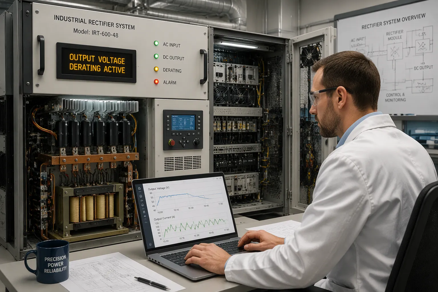
Adaptive multi-stage overload limiting protection keeps a rectifier system running by lowering output voltage in steps as load rises. It does not wait for one fixed threshold and trip. Each stage reduces voltage a little more, so the current stays inside safe limits.
This is a deliberate trade-off. Equipment receives slightly lower voltage, and in return the site stays powered. The alternative is a sudden shutdown that cuts service to every connected load.
The stages differ in trigger point and derating depth. Adaptive control ties them together, sensing load current and deciding when to derate and when to recover.
Key Takeaways
The rectifier lowers the output voltage in steps to keep the current safe and prevent shutdown.
Each stage starts at a different current level and keeps parts safe from harm.
Hiccup mode handles severe overload by shutting off briefly and then trying again.
The system goes back to full voltage on its own when the overload is gone.
This method keeps telecom sites running during overload events.
Overload Limiting in a Rectifier System
The Cost of Unchecked Overload
A rectifier system turns AC input into steady DC output. Too much current for too long puts stress on every part along that path. Silicon Controlled Rectifiers show the danger clearly. A PatSnap technical report describes thermal runaway: higher current density raises junction temperatures, leakage current grows, and more heat follows. This cycle destroys the device. Parallel SCRs seldom share current evenly, and overload makes the imbalance worse until one device carries too much of the load.
Low input voltage makes the problem worse. Industrial Monitor Direct notes that at 90 VAC input versus a nominal 120 V, input current rises about 33 percent at constant load. A weak low-voltage cutoff leaves the input choke and rectifier diodes open to that sustained overcurrent. Unchecked overload ends in damage or a full shutdown.
From Fixed Limiting to Adaptive Staging
A single fixed current limit trips at one threshold. Staged limiting works differently. Current limiting circuits sense load current and adjust load voltage to hold current flow back. A current limiting circuit acts early, before the load reaches a dangerous level. Current-limiting circuits then fold the voltage back in steps. Each current limiting circuit in the chain has its own trigger point. Current limiting circuits at the first stage hold the current steady. Current-limiting circuits at deeper stages cut voltage further. A well-tuned current limiting circuit avoids a hard trip. Current limiting circuits and current-limiting circuits work as one sequence. A current limiting circuit at the last stage hands control back. Current limiting circuits stay coordinated. Current-limiting circuits restore full voltage once the load falls.
Related adaptive behaviors handle transients. Soft start ramps the output up gradually. Overvoltage protection clamps the output during surges. Active current limiting adds a fast response layer. A hybrid overload current limiting and short circuit protection scheme combines these layers. An adjustable current limiter sets the current limit threshold. A current limiter circuit holds the ceiling. A hybrid current limiting technique blends linear and switching response. Short circuit protection and overcurrent protection cover extreme cases. This layered power supply protection keeps the unit online.
The Multi-Stage Derating Sequence
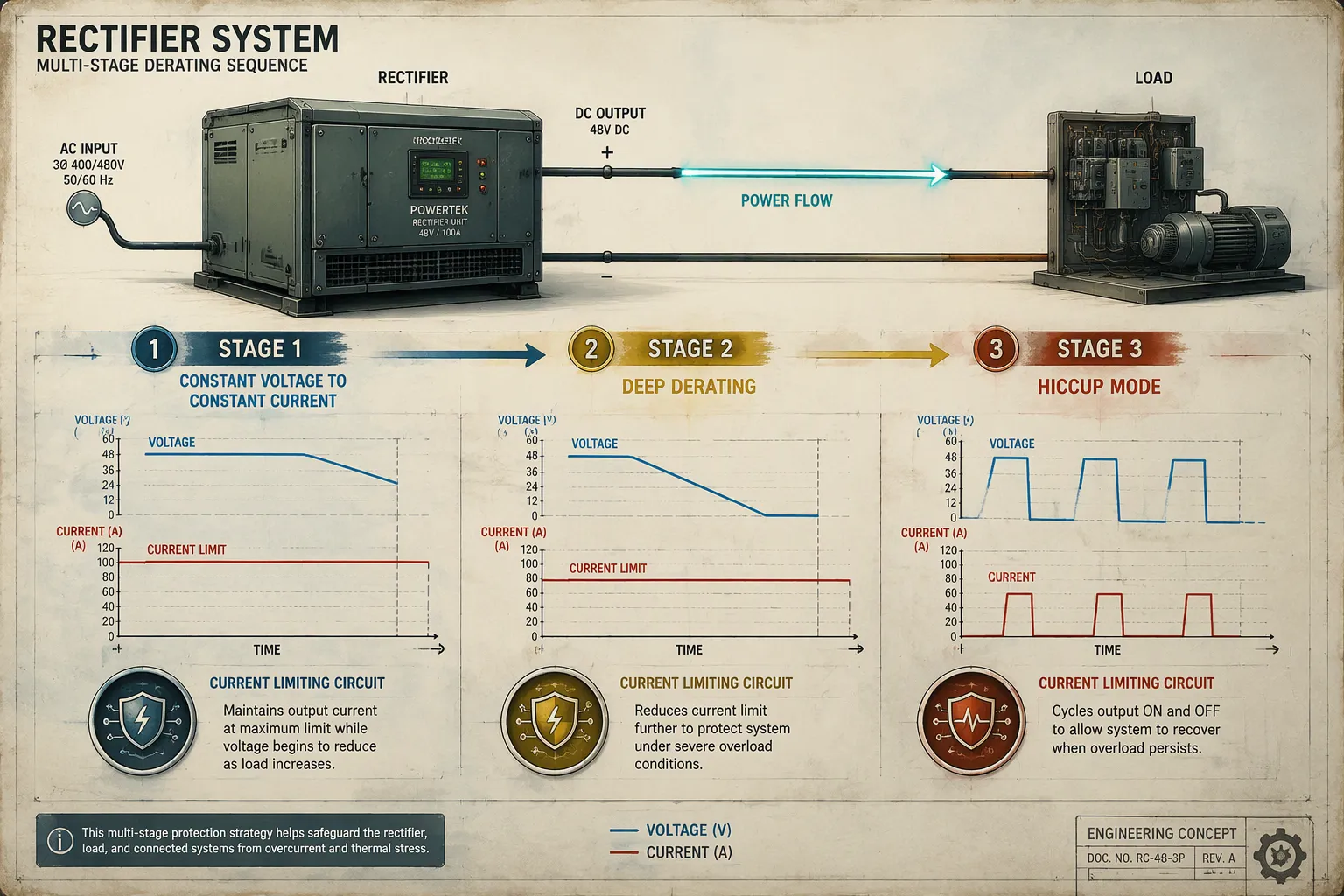
The sequence goes through three stages. Each stage has its own trigger, its own voltage behavior, and its own way of easing the overload.
Stage 1: Constant Voltage to Constant Current
The rectifier system keeps a steady output voltage while the load stays below the current limit. When load current rises past that point, the unit enters Stage 1. Regulation shifts from constant voltage to constant current. The output voltage starts to fold back. A current limiting circuit takes charge here and holds the current at the ceiling instead of letting it climb. The foldback is gentle at first. Connected equipment sees a small dip, and the current stays inside the maximum allowable current. This first step eases overload without any interruption. A current limiting circuit senses the load and adjusts voltage to restrict current flow. The transition is smooth, and the load keeps running.
Stage 2 and 3: Deep Derating and Hiccup Mode
A heavier load pushes the unit into Stage 2. The trigger is a current that stays above the first ceiling. Voltage drops further, and power stays within safe limits. This deeper derating margin protects the semiconductors and the transformer. A current limiting circuit at this level cuts voltage harder. Current limiting circuits coordinate the drop with the earlier stage. The current-limiting circuits keep the output stable while the voltage falls. A current limiting circuit guards the power stage. Current limiting circuits hold the line. The current-limiting circuits prevent thermal runaway. A current limiting circuit responds within the loop. Current limiting circuits share the burden. The current-limiting circuits stay in step. A current limiting circuit backs the sequence. Current limiting circuits restore order. The current-limiting circuits hand control forward. A current limiting circuit closes the loop. Current limiting circuits finish the job. The current-limiting circuits wait for recovery.
Stage 3 covers severe or sustained overload. Deep derating applies, or the unit enters hiccup mode. EEVblog describes the behavior: the supply shuts off, tries to restart, sees the excessive load still present, and shuts off again. A brief output appears every second or so. The supply is off most of the time, and this reduces average output current. Hiccup mode suits short circuit and overload conditions. Short circuit protection and overcurrent protection cover the extreme case. An adjustable current limiter sets the current limit thresholds. Active current limiting adds a fast layer. A hybrid overload current limiting and short circuit protection scheme blends these responses. When overload current falls back within the specified range, the load transfers back to normal operation automatically. The stages reverse in order, and full voltage returns.
Adaptive Control in the Rectifier System
Load Sensing and Feedback Loops
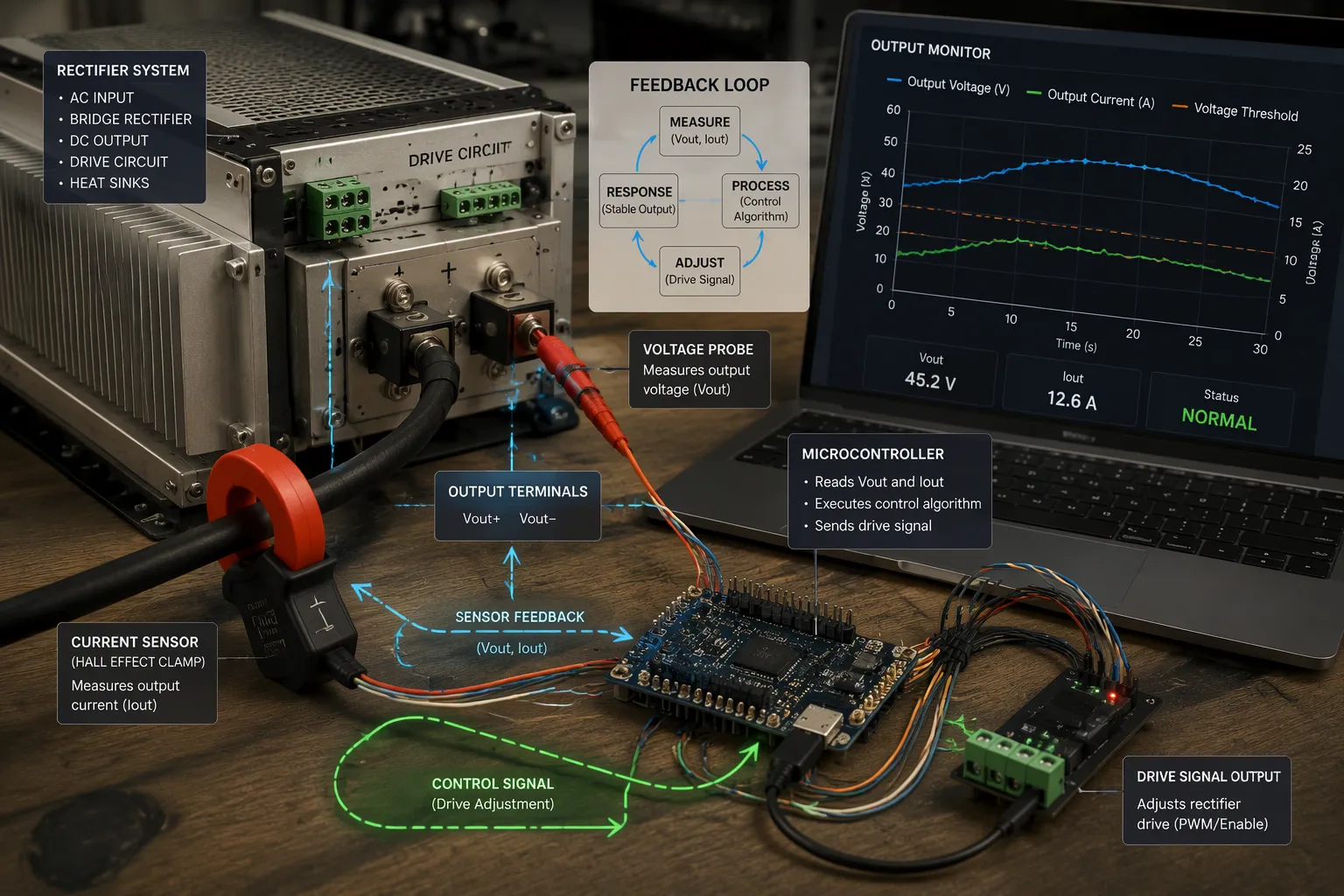
Adaptive control begins with measurement. The rectifier system checks load current and output voltage many times every second. A current limiting circuit compares each reading to its reference. If the output voltage drifts, a correction is triggered. The current limiting circuit then adjusts the drive signal to keep the output steady.
This is a closed loop. A current limiting feedback loop holds the output voltage within a tight range, about ±1%, as load conditions change. The loop reacts to small changes before they become a fault. A current limiting circuit at the sensing stage sends data forward. Current limiting circuits at later stages use that data to set their own thresholds. The current-limiting circuits share one measurement chain. Current limiting circuits therefore agree on when derating should start.
The loop also watches for overload. When current rises past the current limit, the system moves toward Stage 1. The current limiting circuit does not wait for a hard fault. It folds the voltage back early. Current-limiting circuits keep the output stable during this shift. A current limiting circuit guards against false trips. Current limiting circuits confirm the condition before acting. The current-limiting circuits then report the event upward.
Microcontroller-Driven Transitions
A microcontroller decides when to move between stages and when to recover. It reads the sensor data and applies a decision rule. A study in PMC describes one approach: a control gate selects one of three operational modes—Performance, Balanced, or Protection—based on the real-time system state. The logic runs as a table-driven neural-logic hybrid framework. This design fits low-power microcontroller units and keeps response times short.
Aspect | Description |
|---|---|
Mode selection logic | A control gate picks Performance, Balanced, or Protection mode from the real-time system state, using a table-driven neural-logic hybrid framework on low-power MCUs |
Safe mode trigger | Logic and Stateflow, 50 Hz, hard real-time, linked to MHI and temperature limits |
Hysteresis control stops chatter at each boundary. The PMC study ties its safe mode trigger to a 50 Hz hard real-time loop. A combined current limiting algorithm runs inside that loop. The microcontroller sets the adjustable current limiter and the current limit for each stage. It also manages active current limiting during fast transients. Recovery follows the same logic in reverse. Once overload clears, the microcontroller steps the system back to normal output.
Highly integrated protection ICs support this work. They provide current and voltage protection up to specified ratings. Overcurrent protection and short circuit protection sit in hardware, so the microcontroller handles only the staging decisions. This division keeps current limiting performance predictable. The rectifier returns to full output only when the current falls inside the safe range.
Benefits for ESTEL Telecom Power Systems
Preventing Shutdown and Protecting Components
The staged mechanism turns a hard failure into a managed event. A rectifier system that derates in steps avoids the sudden trip that cuts power to every load on the bus. Each current limiting circuit acts before damage begins. The first current limiting circuit folds voltage back early. Deeper current limiting circuits cut harder when the load keeps rising. This layered response protects the semiconductors, the transformer, and the output stage from thermal stress.
Component protection depends on speed and coordination. A current limiting circuit senses the rise in current and corrects the drive signal within the loop. Current limiting circuits at each stage share one measurement chain, so they agree on the trigger point. Current-limiting circuits confirm the condition before acting, which prevents false trips. Current limiting circuits then hold the output steady while the event passes. Current-limiting circuits restore normal operation once the load falls back. Overcurrent and short circuit protection sit in hardware as a final guard. That guard covers the extreme case the staging sequence cannot absorb.
Stability Under Sustained Load
Sustained load is the harder test. A brief surge passes quickly, but a long draw keeps pressure on the output stage. The derating sequence holds voltage inside a tight band during that period. The load keeps running at reduced voltage instead of dropping offline. Stability comes from the feedback loop, which corrects drift continuously. The current limit stays fixed while voltage adjusts around it.
The ESTEL Telecom Power System applies this approach in a practical package. It accepts an AC input range of 90–300 Vac, so it tolerates wide swings at the site. Natural cooling removes the need for fans. The unit installs on a standard 19-inch rack or inside a cabinet. Output current reaches up to 150A. These traits suit sites that need steady power through overload events without an interruption.
Staged, adaptive voltage derating eases overload in steps. A current limiting circuit folds the output back early. Deeper current limiting circuits cut harder when the load keeps rising. Each stage triggers on current and derates voltage, so the system avoids a hard shutdown.
The current-limiting circuits keep things stable through sustained load. A current limiting circuit checks the condition first. Current limiting circuits then bring back full output once current falls. This protection fits modern rectifier systems, where staying online matters more than a fixed trip point.
FAQ
How does the rectifier lower output voltage without shutting down?
The control loop senses load current going up and switches from constant voltage to constant current. Output voltage then folds back in steps. Each step keeps the current under a safe ceiling, so the site keeps running at lower voltage instead of tripping offline.
What triggers the move from one derating stage to the next?
Each stage has its own current threshold. A load that stays above the first ceiling pushes the unit into deeper derating. Severe or long overload can bring on hiccup mode. The system steps back to normal operation once the load falls within range.
Why is hiccup mode used for severe overload?
Hiccup mode shuts the output off, retries briefly, and shuts off again while the fault remains. The supply stays off most of the time, which cuts average output current. This behavior suits short circuit protection and extreme overload cases that staging alone cannot absorb.
How does the system recover after the overload clears?
A microcontroller watches load current and output voltage all the time. When the current drops back inside the safe range, it reverses the stage sequence. Full output returns on its own, and the feedback loop holds regulation within about ±1%.
Does staged derating protect the rectifier hardware?
Yes. Early voltage foldback limits thermal stress on the semiconductors and the transformer. Hardware-level protection ICs add a final guard for overcurrent and short circuit events. The staged response and the hardware guard work together to prevent damage.
See Also
A Guide to Global Standards for Communication Power Supply Systems
Analyzing Amperage Requirements for Communication Cabinet Power Supply Units
How ESTEL Guarantees Correct Voltage Levels for Communication Cabinet Systems
Methods to Achieve Reliable Power Supply for Telecom Cabinet Operations
Calculation Methods for Telecom Cabinet Power Systems and Telecom Batteries
CALL US DIRECTLY
86-13752765943
3A-8, SHUIWAN 1979 SQUARE (PHASE II), NO.111, TAIZI ROAD,SHUIWAN COMMUNITY, ZHAOSHANG STREET, NANSHAN DISTRICT, SHENZHEN, GUANGDONG, CHINA
