Rapid Deployment Solution for Telecom Power Systems with 2-Hour Single-Site Setup


You can complete a single-site setup in two hours. This goal is achievable today with standardized components and a structured process. You likely wonder about feasibility, required steps, common challenges, benefits, and the best recommendations. This article delivers a practical walkthrough. You will discover standardized components, a detailed 2-hour workflow, real case examples, and selection guidance. ESTEL serves as a reference solution throughout. Telecom Power Systems built with modular, factory-tested designs make rapid deployment a repeatable outcome. The following sections show you exactly how to achieve this speed at your own sites.
Key Takeaways
Use factory-tested modular components for quick mounting and connection.
Pre-configure equipment and pre-wire cables before arriving at the site.
Train your team to follow a fixed installation sequence without deviation.
Plan for future capacity with modular designs that scale easily.
Reduce labor costs and speed up network rollout with standardized deployment.
Why 2-Hour Setup Works for Telecom Power Systems
Rapid Setup Overview
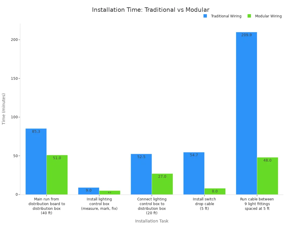
Standardized, modular, and pre-assembled Telecom Power Systems change the deployment timeline. Instead of wiring each component on-site, you receive factory-tested modules requiring only mounting and connection. Time savings across every installation task are substantial. A traditional main run from a distribution board to a distribution box takes 85.30 minutes. Modular wiring completes the same task in 51.00 minutes. Installing a switch drop cable drops from 54.70 minutes to 8.00 minutes. Running cable between nine light fittings drops from 209.90 minutes to 48.00 minutes. The labor rate shifts from $95.00 per hour for an on-site electrician to $35.00 per hour for factory assembly work.
This efficiency extends to complete site deployments. A telecom operator needed to deploy a new site in a remote mountain area. Using ESTEL's modular outdoor cabinets and Telecom Power System, the installation team completed the setup in just two hours. The site became operational without delays. The modular design enabled quick assembly and connection of all components. This deployment proves that a 2-hour single-site setup is repeatable, not a one-time exception.
Key Success Factors
Three factors determine whether you can achieve this speed. First, you need pre-engineered components designed for rapid integration. Factory-tested modules eliminate on-site troubleshooting. Every part connects seamlessly without custom adjustments. Second, trained field teams must understand the specific process. Repeated drills build muscle memory and confidence. A team encountering standardized equipment for the first time cannot complete the setup in two hours. Third, you require a repeatable process with clear checklists, pre-staging procedures, and documented handoff criteria. Following the same sequence every time builds consistency and speed.
This approach works best for new sites with standardized layouts. Non-standard or legacy sites with mixed equipment require additional time for compatibility checks and custom adapters. For standard deployments, these three factors transform a 2-hour setup from an ambitious target into a reliable metric you can count on.
Traditional Deployment Challenges vs. Standardized Approach
Common Pain Points of Traditional Builds
Traditional telecom power deployments rely on custom-built, on-site assembly. This approach creates several persistent problems. Long lead times top the list. You wait for multiple vendors to deliver separate components, then coordinate their arrival at the site. Wiring errors happen frequently because field teams work with unfamiliar configurations under time pressure. A single misconnection can delay commissioning by hours or days. Multiple vendor coordination adds another layer of complexity. Rectifiers, distribution panels, batteries, and controllers often come from different suppliers. Each vendor follows its own documentation, connector types, and testing procedures. Your field team must reconcile these differences on-site, which slows every installation step.
These pain points compound each other. A wiring error discovered during commissioning forces the team to trace cables, consult multiple manuals, and possibly wait for replacement parts. Network uptime suffers when sites remain offline longer than planned. Labor costs rise because skilled electricians spend hours on troubleshooting instead of installation. The traditional model works, but it does not scale efficiently for rapid rollout programs.
How Standardization Removes Barriers
Standardized, factory-tested modules eliminate these barriers directly. You receive pre-engineered components that arrive ready for mounting and connection. The factory performs all wiring verification and functional testing before shipment. On-site assembly becomes a simple sequence of mounting, connecting AC input, connecting DC output, and linking communication ports. This shift removes the need for multiple vendor coordination because one supplier delivers the complete power system.
The outcomes are measurable. Cost reduction comes from lower labor rates and fewer hours per site. The completed article's evidence shows modular wiring completing tasks in roughly half the time of traditional methods. Reliable network uptime improves because factory testing catches defects before deployment. Faster installation follows naturally from the simplified process. You deploy more sites with the same team, which supports 5G and edge expansion targets. Standardization turns deployment from a variable, risk-heavy project into a predictable, repeatable operation.
Standardized Components That Enable Speed
What Standardized Components Are
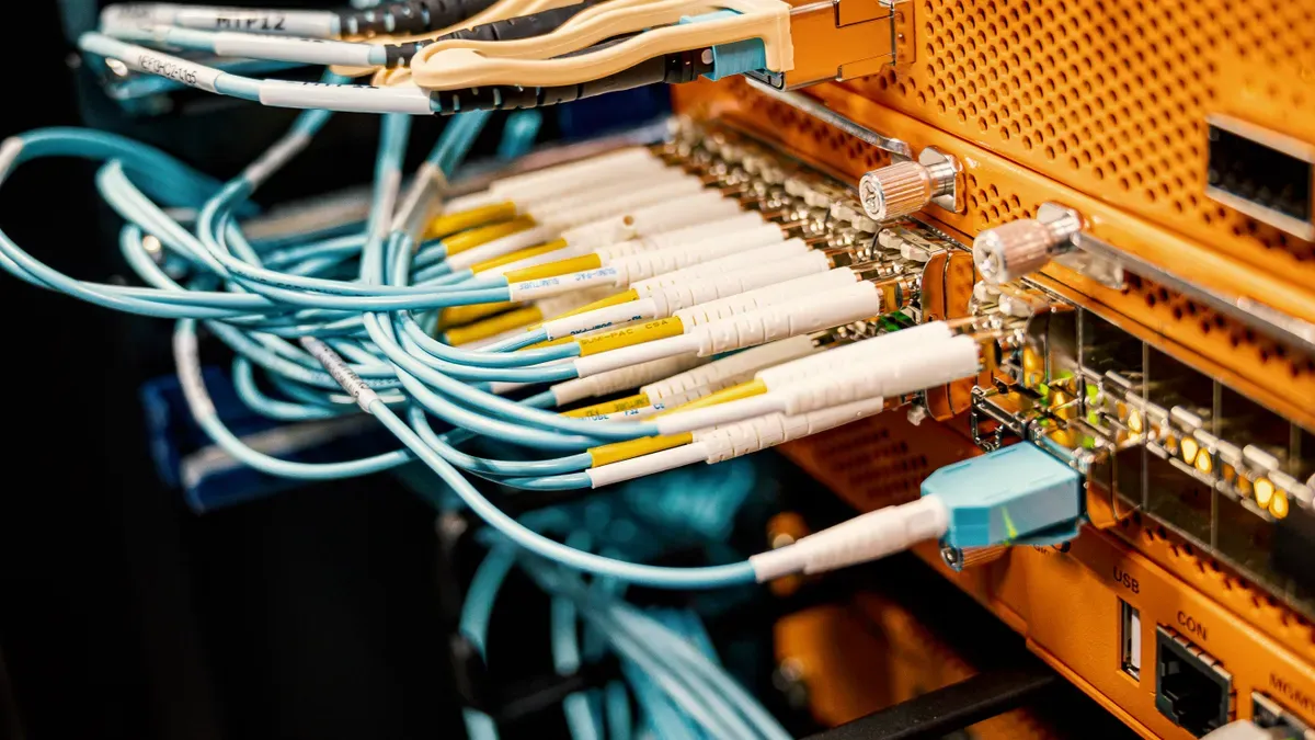
Standardized components are pre-engineered, interchangeable, and factory-tested modules. They include rectifiers, distribution units, batteries, and controllers. Each module follows a common interface specification. You can swap one unit for another without custom wiring or firmware changes. This design philosophy removes the guesswork from field installation.
The telecom industry builds these components around several core characteristics. A modular and scalable rectifier architecture uses high-frequency switch-mode power supply technology. This allows flexible system expansion and quick capacity additions without major redesign. A standardized -48V DC architecture ensures compatibility between legacy and modern equipment. Compact designs with low heat dissipation reduce the physical footprint. Lower current in -48V DC systems permits smaller cables and easier routing. Redundancy architectures such as N+1 and N+N configurations improve reliability and fault tolerance. Dual-feed DC bus architectures maintain operation during failure or maintenance.
Formal standards define how these components must behave. NEBS (Network Equipment-Building System) provides the overarching certification framework. GR-63-CORE specifies physical and environmental requirements, including temperature, humidity, fire spread, vibration, and earthquake tolerance. GR-1089-CORE covers electrical safety and electromagnetic requirements, such as grounding, electrostatic discharge protection, and lightning resistance. SR-3580 maps deployment environments to specific compliance levels. These standards give you confidence that any certified module will perform predictably.
Inside the ESTEL Telecom Power System
The ESTEL Telecom Power System exemplifies this standardized approach. It mounts on a standard 19-inch rack or inside a cabinet. Natural cooling eliminates the need for fans or additional cooling equipment. The system accepts an AC input voltage range from 90 to 300 Vac and delivers DC output with a maximum output current of up to 42A (for a 2000W system).
Specification | Value |
|---|---|
Cooling mode | Natural cooling |
Installation mode | 19-inch rack or inside cabinet |
Input Voltage | 90–300 Vac |
Output Current (max, 2000W system) | 42 A |
These strengths translate directly into deployment speed. The wide input voltage range handles unstable grid conditions without additional voltage regulators. Natural cooling lowers maintenance requirements because there are no moving parts to fail. Easy integration into standard racks and cabinets means your team spends minutes mounting the unit, not hours fabricating custom brackets. Seamless networking through multiple communication ports allows remote monitoring from day one. When you deploy Telecom Power Systems built to these specifications, every site follows the same predictable installation sequence.
Step-by-Step Guide to the 2-Hour Setup

Preparation Before Site Arrival
Preparation determines whether your team finishes in two hours or spends the day troubleshooting. You complete most of this work before anyone arrives at the site. Start with a site survey. Confirm the rack or cabinet dimensions, verify the AC supply capacity, and check the cable routing path. Document the DC load requirements and the distance to the equipment you will power. This survey prevents surprises on installation day.
Pre-configuration comes next. Set the output voltage and current limits on the ESTEL Telecom Power System at your staging facility. Verify the rectifier module operates correctly under load. Pre-wiring saves critical minutes. Prepare AC input cables, DC output cables, and communication cables with correct connectors already attached. Label every cable at both ends. Your tool and material checklist should include a torque wrench, multimeter, cable ties, mounting screws, and personal protective equipment. Assign clear team roles. One technician handles mechanical mounting. Another manages electrical connections. A third person performs commissioning checks and documents results.
Installation and Commissioning
Installation follows a fixed sequence. Mount the ESTEL Telecom Power System on the 19-inch rack or inside the cabinet using the provided hardware. The unit is designed for easy handling. Tighten all mounting screws to the specified torque. Connect the AC input cable to the terminal block. The wide input voltage range of 90 to 300 Vac accepts your prepared cable without additional voltage conditioning equipment. Connect the DC output cable to the distribution terminals. Attach the communication cables to the designated ports for remote monitoring and network integration.
Commissioning validates the installation. Power on the system and observe the startup sequence. Verify the output voltage meets system specifications. Measure the output current and confirm it matches your site load requirements, up to the system's rated maximum output current (e.g., 42A for a 2000W system). Test each communication port to ensure data flows to your network management system. Complete the handover documentation with measured values, serial numbers, and installation dates.
Phase | Key Tasks |
|---|---|
Preparation | Site survey, pre-configuration, pre-wiring, tool check, role assignment |
Installation | Rack mounting, AC input connection, DC output connection, communication port connection |
Commissioning | Power-on checks, voltage/current verification, communication testing, documentation |
This sequence delivers a reliable two-hour completion for standard site conditions and a trained team. Non-standard sites may require additional time for compatibility checks. For standard deployments, this sequence delivers a reliable two-hour completion. Teams that follow this process consistently deploy Telecom Power Systems faster and with fewer errors than teams using traditional assembly methods.
Real-World Results, Benefits, and Recommendations
Case Studies and Lessons Learned
A telecom operator needed to deploy a new site in a remote mountain area. Using ESTEL's modular outdoor cabinets and Telecom Power Systems, the installation team completed the setup in just two hours. The site became operational without delays. The modular design enabled quick assembly and connection of all components. This deployment proves that a 2-hour single-site setup is repeatable, not a one-time exception.
The key lesson from this project: pre-staging all cables and pre-configuring the system at the staging facility saved critical minutes. Team training also mattered. Crews that had practiced the sequence completed the work faster and with fewer errors.
Benefits, Considerations, and Choosing the Right Solution
Standardized deployment delivers measurable benefits for operators. Labor costs drop because modular wiring completes tasks in roughly half the time of traditional methods. Fewer wiring errors occur because factory testing catches defects before shipment. Faster rollout supports 5G and edge site expansion targets. Easier scaling means you add capacity without replacing the entire system.
You must evaluate several considerations before selecting a solution. Site conditions, legacy equipment compatibility, training needs, and future capacity planning all affect your deployment speed. Check that physical dimensions fit within the cabinet's available space. Verify input and output connections align with your power supply and equipment needs. Confirm proper grounding and secure installation to prevent hazards. Follow local regulations regarding height, grounding, and permits.
Certifications validate quality and safety. Look for these marks when choosing a standardized power system.
Certification | Purpose |
|---|---|
ISO9001 | Confirms consistent manufacturing processes for quality assurance |
UL | Confirms compliance with electrical safety standards |
RoHS | Addresses environmental impact and safety |
CE | Confirms compliance with health, safety, and environmental protection standards |
VDE | Validates electrical safety and performance standards |
Choose standardized, modular solutions like ESTEL's Telecom Power System. Plan for future capacity and scalability. Assess total cost of ownership, which includes purchase price, maintenance expenses, energy consumption, and potential downtime costs. A higher initial price may be justified by better durability, energy efficiency, and scalability.
You now see that a two-hour single-site setup is a repeatable outcome of standardization, preparation, and modular design. This approach delivers faster rollout, lower labor costs, fewer errors, and easier scaling. Evaluate standardized Telecom Power Systems like ESTEL for your next deployment. Plan for future capacity needs by selecting scalable architectures.
Industry projections reinforce this urgency. The global market grows at 8.12% annually through 2035, with Asia-Pacific leading at 9.4%. Modular DC platforms and lithium-ion integration will dominate. Rapid deployment positions you to support 5G and edge site expansion. Begin your transition today.
FAQ
What makes a 2-hour single-site setup possible?
You rely on three elements working together. Pre-engineered, factory-tested modules remove on-site assembly work. A trained crew follows a fixed sequence without hesitation. A documented process with pre-staging and clear checklists keeps every deployment consistent. Remove any one element, and your completion time stretches beyond the two-hour target.
Can you deploy this system at legacy or non-standard sites?
Standard layouts reach the two-hour mark reliably. Legacy sites with mixed equipment demand extra time for compatibility checks and custom adapters. Survey the site first. Confirm rack dimensions, AC supply capacity, and DC load requirements before you commit to a schedule.
What training does your field team need?
Your crew must practice the mounting, wiring, and commissioning sequence repeatedly. Teams encountering standardized equipment for the first time cannot finish in two hours. Assign clear roles: one technician mounts, one connects cables, one commissions and documents. Repeated drills build the muscle memory that delivers consistent speed.
How does the ESTEL Telecom Power System simplify installation?
The unit is compact and easy to handle. Natural cooling removes fan maintenance. The 90–300 Vac input range accepts unstable grid power without extra voltage conditioning equipment. Multiple communication ports enable remote monitoring from day one.
Does standardization limit future capacity expansion?
No. Modular architectures let you add rectifiers and batteries as load grows. You scale capacity without replacing the entire system. Plan your initial installation with spare rack space and distribution capacity. This forward-looking approach supports 5G and edge site expansion without a full redesign later.
See Also
Solar Powered Battery Backup System For Telecommunication Cabinet Enclosures
Methods To Guarantee Continuous Electrical Supply For Telecom Cabinet Equipment
Grid Tied Solar Inverter With Battery Storage Solution For Telecom Cabinets
Calculating Telecom Cabinet Power Requirements And Battery Capacity Sizing
ESTEL Smart Microgrid Telecom Cabinet Battery Energy Storage Integration
CALL US DIRECTLY
86-13752765943
3A-8, SHUIWAN 1979 SQUARE (PHASE II), NO.111, TAIZI ROAD,SHUIWAN COMMUNITY, ZHAOSHANG STREET, NANSHAN DISTRICT, SHENZHEN, GUANGDONG, CHINA
