Early Warning and Linkage of Battery Compartment Thermal Runaway in Telecom Power Systems: Constructing Multi-Layer Comprehensive Safety Defenses

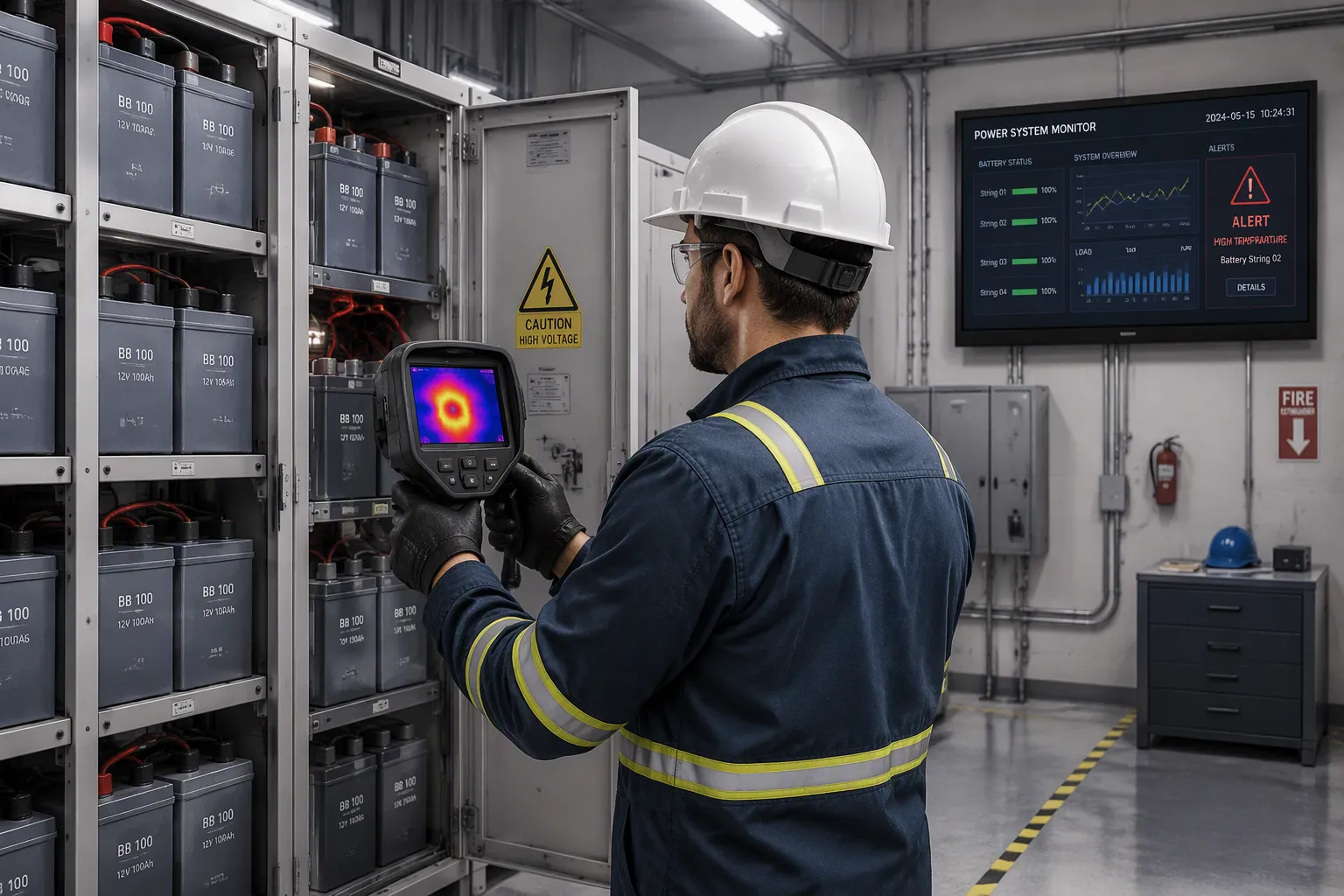
Four defense layers protect a battery compartment from thermal runaway: early detection, intelligent warning, linkage response, and containment. This article explains how to build each layer and how to connect them into one working chain.
Telecom battery compartments carry a distinct risk profile. Sites often run unattended, batteries charge continuously, and cabinets may house mixed chemistries side by side.
Practical selection and integration guidance follows, including where ESTEL monitoring and linkage solutions fit within each layer. Readers will finish able to specify a layered defense architecture for telecom power systems that matches their own site profile and raises overall safety.
Key Takeaways
Early detection catches battery problems 15–45 minutes before failure, so you can act in time.
Place sensors at the cell level to detect the earliest signs of trouble.
Automated linkage turns warnings into actions like shutting off power and starting fire suppression.
Combine multiple defense layers—detection, warning, response, and containment—for the best protection.
Test the entire safety chain regularly to ensure it works when needed.
How Thermal Runaway Starts in Telecom Batteries
Thermal runaway is a chain reaction. Internal temperature rises uncontrollably, and the cell releases heat, gas, smoke, fire, or explosion. The root cause is simple: heat generation outpaces heat dissipation. In a sealed telecom cabinet, that imbalance can build quietly for a long time before anyone notices.
Trigger Conditions and Precursor Signals
Several conditions start the chain. Internal short circuits, overcharging, cell degradation, and external heat all push a cell toward instability. Each condition leaves detectable traces before failure.
Signal Category | Precursor / Trigger Indicator |
|---|---|
Electrical (voltage/current) | Abnormal voltage drops, current spikes, irregular charging patterns signaling internal short circuits or cell degradation |
Thermal | Abnormal temperature rise detected via multi-point sensors, thermal imaging, and distributed temperature sensing to catch localized hot spots |
Gas & pressure | Hydrogen/other gas emissions and internal pressure buildup within the enclosure |
Impedance | Changes in impedance and internal resistance detectable via electrochemical impedance spectroscopy / AC impedance measurements |
Integrated multi-parameter | Fusion of temperature, voltage, current, gas concentration, and acoustic emissions with graduated warning levels |
Quantified thresholds sharpen the picture. A temperature gradient acceleration exceeding 5°C per minute signals danger. A voltage drop rate surpassing 0.1V per cell within 60 seconds is another red flag. Internal pressure buildup beyond design thresholds adds a third. Notably, 78% of thermal runaway incidents show detectable precursor signals 15–45 minutes before critical failure. That window makes intervention possible.
Progression From Cell to Compartment
A thermal runaway event rarely stays confined. Heat from one failing cell spreads to neighbors, and the process escalates. Off-gassing and voltage anomalies appear first at the cell level. The battery management system, or BMS, can flag these anomalies early. Multi-point sensing then tracks the spread across modules.
Chemistry shapes the risk profile. Lithium-ion cells warrant particular attention because they store high energy density and can vent flammable gas. Lead-acid designs behave differently but still demand respect. Both chemistries benefit from layered battery safety design. In a lithium-ion battery energy storage system, or BESS, propagation from cell to compartment is the central concern. BESS fires often begin with a single cell, and lithium-ion battery fires spread fast once gas ignites. The same logic applies to telecom cabinets and larger lithium-ion BESS installations. A robust BMS and a battery management system architecture that fuses multiple parameters reduce fire risk substantially. Understanding this progression is the foundation for every safety layer that follows.
Early Warning Technologies for Battery Thermal Runaway
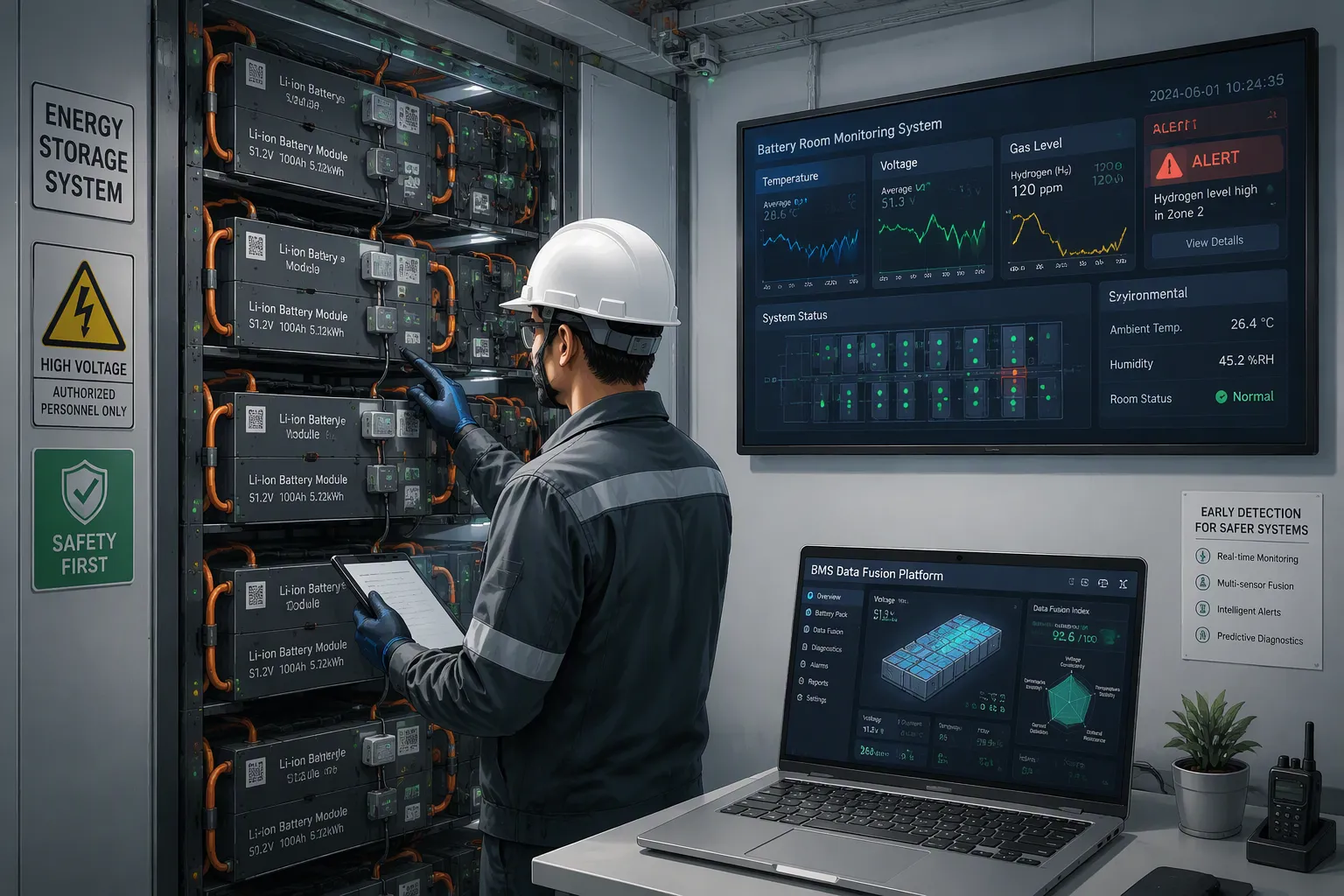
Advanced detection and early warning systems identify potential thermal runaway conditions before they escalate. A well-designed layer buys time, and time is the currency of every response that follows.
Temperature, Gas, and Voltage Sensing
Researchers have established a three-level thermal runaway early warning method under high-stress conditions. Multi-scale spatiotemporal attention networks can deliver reliable warning using only existing BMS voltage and temperature sensors. This matters for operators who want better warning without adding hardware everywhere.
Temperature rise rate remains the clearest single indicator. The table below maps measured thresholds to progression stages in lithium-ion cells.
Stage | Temperature rise rate threshold | Associated behavior |
|---|---|---|
Stage II | Above 0.0025 °C per second | Cell bulging from gas generation; electrolyte evaporation and SEI decomposition |
Stage IV | Above 0.2 °C per second | Violent exothermic reactions; anode decomposition and micro internal short circuits |
Stage V | Above 1 °C per second | Abrupt thermal runaway with large gas and heat release |
Voltage anomalies complement thermal data. Cell voltage drops and impedance changes can flag a failing cell before temperature escalates. Voltage alone can resemble noise, so fusion with other channels sharpens the picture. Gas detection adds a chemical channel: sensors catch off-gassing and electrolyte decomposition products before significant temperature rise or fire. Multi-gas arrays improve accuracy and cut false alarms. A gas detection system paired with a real-time BMS gives responders two independent views of the same event. Multi-parameter fusion that combines temperature, voltage, current, pressure, and gas detection with machine learning improves detection accuracy and shortens response time. For any BESS, this fusion approach outperforms single-parameter methods. ESTEL sensing and monitoring hardware fits this role as one option among several, positioned by application fit.
Sensor Placement for Fastest Response
Placement decides detection speed. Thermal runaway originates inside a single cell, and the initial anomaly of 1–3 °C appears only on that cell. A sensor on that cell captures it at the earliest stage, before heat conducts elsewhere.
Placement strategy | Detection speed | Rationale |
|---|---|---|
Cell-level (cell thermal center) | Fastest | Captures the initial anomaly on the affected cell |
Cell-level (tab or terminal) | Very fast for connection faults | Detects resistive heating at degraded welds before arcing |
Cell-level (inter-cell gap) | Fast for propagation containment | Captures temperature at the propagation boundary |
Module-level | Slower | Event registers only after heat crosses multiple cells |
A module-level sensor sits several cells away and misses the event until heat conducts through intervening cells. That delay of seconds to minutes separates successful intervention from cascading failure. Per-cell sensing at the thermal center and inter-cell gap provides the earliest possible detection. Compartment-level placement deserves attention too, and a fire detection system at that level covers the space between modules. Gas detection at the compartment level catches accumulated vapors that cell sensors may miss. Layered gas detection across cell, module, and compartment levels strengthens overall safety. Operators building a BESS or upgrading a telecom cabinet should treat placement as a design decision, not an afterthought. The battery management system reports what its sensors see, and sensor position determines what those sensors can see. Good safety outcomes start with coverage, and coverage starts at the cell.
Linkage Mechanisms That Turn Warnings Into Action
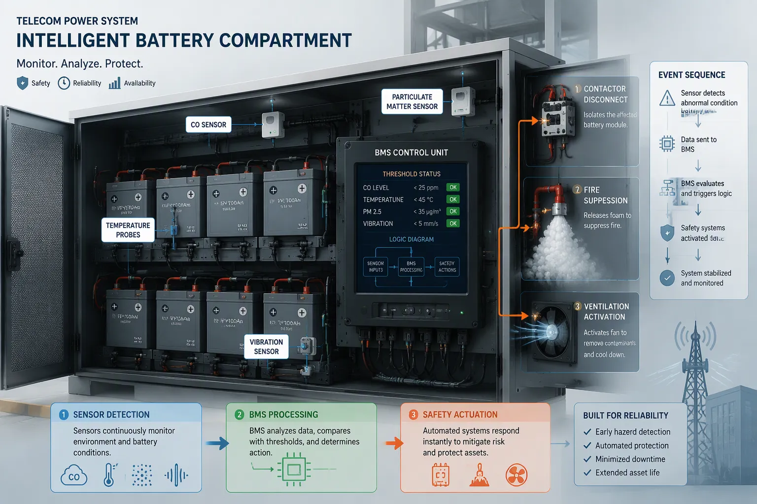
A warning only matters when it changes physical behavior. Linkage logic converts an alarm into a sequence of automated actions: fast power cut, charging shutdown, and electrical isolation. The trigger thresholds decide when that sequence begins.
Parameter | Warning Level | Critical Level | Recommended Action |
|---|---|---|---|
CO concentration | 5–25 ppm | >50 ppm | Isolate cell/module; activate fans |
Particulate matter | 0.1 mg/m³ | >1 mg/m³ | Trigger smoke extraction |
Temperature | 60°C (cell) | >80°C (cell) / >70°C (module) | Disconnect BMS; initiate shutdown |
Vibration (RMS) | 0.5–1.0 mm/s | >2.0 mm/s | Predictive maintenance alert |
Charging Shutdown and Electrical Isolation
The control chain follows a fixed order. Sensors send raw readings to the BMS through analog or digital channels. The BMS applies Kalman filtering for noise reduction and moving-average trend analysis. Alerts fire when two or more sensors exceed their thresholds together, so a CO reading plus a temperature spike carries more weight than either signal alone. Multi-sensor AND logic replaces single-sensor trips.
Actuation then proceeds in layers. Primary action disconnects faulty cells or modules through contactors or fuses. Secondary action releases fire suppression, such as AFFF foam or CO₂ flooding. Tertiary action runs an emergency shutdown and ventilation purge. This staged design keeps a minor anomaly from triggering a full site outage.
UL 1973: smoke detection in battery enclosures with response <60 s for thermal events; CO alarm thresholds at ≤25 ppm for early warning; redundant sensor placement in packs >10 kWh.
IEC 62619: particulate matter as a critical safety parameter with alarms at PM10 > 0.5 mg/m³; mandatory interlocking between smoke/CO sensors and battery disconnects; acoustic emission monitoring as optional predictive measure.
Ventilation and Suppression Activation
False trips erode trust in automation, so designers build confirmation into every release path. Reference sensors measure background air and cancel out non-battery signals, such as ambient interferents. A single sensor alert raises only a warning. Full shutdown requires confirmed multi-sensor agreement. Tiered control logic separates low-confidence alerts from confirmed faults, and testing against common interferents such as HVAC fumes keeps nuisance alarms down.
Multi-sensor arrays raise confidence further. Paired gas sensor types, for example hydrogen plus carbon monoxide, detect multiple vapor species and let the system analyze reading patterns. Pressure sensors catch rapid pressure rise from cell venting and trigger immediate shutdown or ventilation before gas reaches external sensors. Aspirating smoke detectors sample air continuously and add a supplementary confirmation layer. Combined gas detection, thermal, pressure, and smoke sensing delivers the earliest possible warning while suppressing false positives. In a BESS, this coordination matters because a thermal runaway event can escalate within minutes. ESTEL linkage controllers serve as one example implementation of this logic, and operators should evaluate them against their own site requirements.
Integrating Multi-Layer Defenses in Telecom Power Systems
No Thermal Propagation, or NTP, treats safety as a system rather than a single barrier. Multi-layer safety design combines active cooling, fast power cut, and passive barriers so a failing cell cannot ignite its neighbors. The BMS, sensors, and cooling channels regulate heat dynamically. Passive barriers contain localized failures when active systems can no longer compensate. Coated fabrics insulate, char, and reflect heat at the point of failure, and integrating them into modules turns passive layers into preventive design elements. This approach slows thermal propagation and buys time for controls to isolate faults.
Detection and Warning Layer Design
Detection and warning layers interconnect with response and containment through shared logic. Real-time temperature, voltage, current, and gas sensing with predictive analytics triggers automatic cell isolation and emergency cooling activation. The battery management system manages charge and discharge parameters, cell balancing, fault diagnosis, and automated emergency procedures. Telecom power systems integrate these layers with site infrastructure and remote monitoring, so an alarm reaches both the local controller and the network operations center.
Immersion cooling offers one strong option for demanding sites. It submerges cells in non-conductive dielectric fluid and removes thermal resistance layers. Reported cooling rates reach up to 0.143°C/s versus 0.037°C/s for air cooling. That speed helps limit propagation of thermal runaway in a battery energy storage system.
Response and Containment Layer Design
Response and containment layers must match the agent to the fire. The table below compares common suppression options.
Suppression Agent | Primary Mechanism | Cooling Capacity | Suitability for Deep-Seated Fires | Post-Fire Cleanup |
|---|---|---|---|---|
Water Sprinklers | Cooling & Wetting | High | Moderate | Difficult (water damage risk) |
Water Mist | Heat Extraction & Oxygen Displacement | Very High | High | Moderate |
Clean Agents (Novec 1230) | Chemical Chain Breaking | Low | Low | Excellent (no residue) |
Aerosols | Chemical Inhibition | Low | Low | Moderate (particulates) |
Operators should request UL 9540A reports to understand thermal runaway containment capability. NFPA 855 sets spacing and stored-energy limits for battery energy storage systems. Damaged cells can reignite hours or days later, so teams use thermal imaging and maintain a fire watch for at least 24 hours. ESTEL integrated defense platforms offer one fit option for operators building layered architectures across telecom power systems, with thermal propagation prevention and multi-layer defenses built into the design.
Comparing Options for Battery Safety
Matching Technology to Site and Chemistry
Sensing, linkage, and suppression options differ in performance, fit, and cost. A comparison helps operators match each technology to the site profile and the chemistry in use.
Suppression Option | Typical Cost | Best-Fit Site Profile | Technical Consideration |
|---|---|---|---|
Pre-action / dry-pipe sprinklers | ~$1–$4 per sq. ft. | Code-baseline, budget-conscious retrofits | Water-based; dual-trigger design reduces accidental discharge risk |
FM-200 | ~$25K–$75K per room | Sites where fast response is critical | High global warming potential; subject to EPA phase-down |
Novec 1230 | ~$30K–$80K per room | Environmentally preferred, insurer-friendly installs | Higher upfront cost than FM-200 |
Inergen (inert gas) | ~$40K–$100K+ per room | Large rooms with strict insurer requirements | Requires more cylinder storage space |
CO2 | Not recommended for occupied rooms | Unoccupied industrial hazards only | Prohibited by OSHA in normally occupied server rooms |
Sensing choices follow the same logic. Microcable offers the strongest strain transfer for high-sensitivity monitoring. Duct cable balances coupling and localization. Anti-rodent cable trades sensing performance for durability and the quietest baseline. Each fits a different environment, and none suits every site.
Standards, Certification, and Lifecycle Cost
Codes shape the shortlist. NFPA 76 requires detection and suppression in telecom switching rooms. NFPA 2001 governs clean agent design and safe concentration. OSHA prohibits CO2 in normally occupied rooms. EPA SNAP restricts high-GWP agents and favors Novec 1230 or Inergen. Insurers such as FM Global often require clean agent systems and early-warning detection for reasonable rates. A lithium-ion BESS in a staffed room therefore rules out CO2 early.
Lifecycle cost extends beyond capital spend. Maintenance, replacement intervals, and testing frequency all matter. Continuous health monitoring through onboard data capture and AI diagnostics tracks usage and health metrics, prevents risks, and lowers warranty and service spend. Integrated platforms optimize maintenance scheduling rather than fixed intervals. End-of-life decommissioning and material recovery add further cost. Operators should weigh these factors against the site profile before committing.
Implementation Best Practices and Field Examples
Commissioning, Testing, and Maintenance
Commissioning proves that every layer works before a real event tests it. Teams inject simulated alarm signals at each sensor and confirm the full chain: sensor, controller, contactor, and suppression release. They verify that the bms reports the same fault the local panel shows. A documented pass on each linkage path prevents surprises later.
Routine testing keeps the chain trustworthy. Operators schedule periodic gas detection checks with calibrated reference gases, confirm sensor drift stays within tolerance, and test contactor response under load. Maintenance routines include cleaning optical smoke sensors, replacing gas sensor elements on the manufacturer's interval, and reviewing alarm logs for nuisance trips. A lithium-ion battery site deserves a shorter inspection cycle than a lead-acid cabinet. Records of every test support insurance reviews and code inspections.
Lessons From Real Deployments
Field experience teaches lessons that datasheets miss. In one ESTEL installation at an unattended telecom site, technicians found that a single module-level sensor missed an early cell anomaly. Adding per-cell sensing at the thermal center cut detection delay sharply. The takeaway: placement decisions deserve review after the first months of live data.
Other deployments show the value of staged linkage. Sites that required two confirmed sensor signals before shutdown reported fewer false trips and steadier operator confidence. Teams also learned to pair remote monitoring with local action, so a network operations center sees the alarm while the controller acts immediately. For any bess, a 24-hour fire watch after a venting event remains standard practice. These examples share one theme: safety improves when detection, warning, and response undergo joint testing, not isolated checks.
Detection buys time. Warning enables decisions. Linkage converts decisions into action. Containment limits damage. These four layers form one chain, and each link strengthens the next.
No single technology carries battery safety alone. Success comes from integration, sensor placement, and tested linkage logic. NTP-oriented design adds passive barriers that slow thermal propagation when active systems fall short. Teams should test every path together, not in isolation.
Modern battery management systems have evolved into comprehensive platforms addressing degradation through predictive analytics and adaptive control, integrating state-of-charge estimation, impedance spectroscopy, and machine learning to assess battery health in real time — enabling proactive intervention before significant degradation occurs.
Smarter analytics and remote monitoring will soon reach most telecom power systems. Evolving chemistries will demand adaptable protocols. Operators should audit each compartment against the four layers, confirm that controls limit propagation of thermal runaway, and verify that BESS cabinets meet the same standard. Regular audits keep thermal runaway defenses current.
FAQ
How early can a monitoring system detect a thermal runaway event?
Most incidents show detectable precursor signals well before critical failure. The completed analysis cites a window of 15–45 minutes in 78% of cases. Cell-level sensors at the thermal center capture the earliest anomaly, so placement matters more than sensor count.
How do operators prevent nuisance shutdowns from false alarms?
Designers require confirmation before full release. A single sensor alert raises only a warning. Two or more sensors must agree before shutdown or suppression fires. Reference sensors cancel ambient interferents, and tiered logic separates low-confidence alerts from confirmed faults.
Does battery chemistry change the defense design?
Yes. Lithium-ion cells warrant particular attention because they store high energy density and can vent flammable gas. Lead-acid designs behave differently but still need layered protection. A bess with lithium cells needs faster detection and stronger propagation barriers than a lead-acid cabinet.
Which standards should guide a telecom battery compartment design?
UL 1973 and IEC 62619 cover battery enclosure detection and interlocking. NFPA 855 sets spacing and stored-energy limits for energy storage systems. NFPA 76 and NFPA 2001 govern telecom room detection and clean agent design. UL 9540A reports show containment capability.
How often should teams test the detection and linkage chain?
Test each linkage path at commissioning with simulated alarm signals. Then schedule periodic gas checks with calibrated reference gases and contactor tests under load. Lithium-ion sites deserve shorter inspection cycles than lead-acid cabinets. Document every test for insurance and code reviews.
See Also
Estel's Complete Guide For Analyzing Risks In Telecom Cabinet Batteries
Why Lithium Batteries Outperform Other Options In Telecom Cabinets
Calculation Methods For Telecom Cabinet Power Systems And Telecom Batteries
How To Guarantee A Reliable Power Supply In Telecom Cabinets
Expert Advice For Protecting Communication Cabinets In High-Risk Locations
CALL US DIRECTLY
86-13752765943
3A-8, SHUIWAN 1979 SQUARE (PHASE II), NO.111, TAIZI ROAD,SHUIWAN COMMUNITY, ZHAOSHANG STREET, NANSHAN DISTRICT, SHENZHEN, GUANGDONG, CHINA
