How Telecom Power Systems with Dual-Bus Architecture Eliminate Single Points of Failure in Financial Data Centers

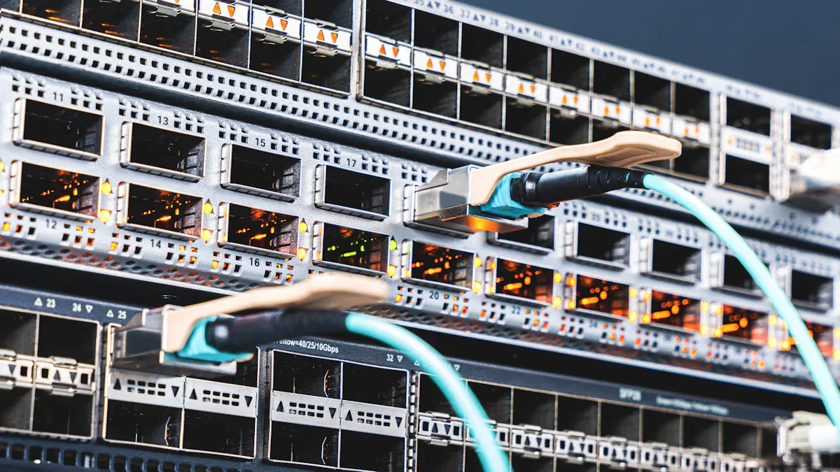
A dual-bus telecom power architecture removes the single point of failure risk. It gives two independent power paths with full redundancy, from utility input to the critical load. Financial data centers cannot handle any interruption. A 2016 Ponemon Institute study found average unplanned outage costs at $8,851 per minute. Even short outages can stop transactions, cause regulatory penalties, and harm customer trust.
This danger exists whenever one component's loss stops the whole system. One rectifier, one battery string, or one shared bus can bring everything down.
Operators should ask whether their telecom power systems can survive a single component failure. A tier 4 data center needs continuous uptime. Every path must have a backup.
Key Takeaways
A single point of failure can take down the entire power system. Dual-bus architecture gets rid of these risks by using two separate power paths.
A dual-bus design keeps important equipment running even if one bus stops working. This helps financial data centers stay online without any breaks.
Operators can work on or upgrade one bus while the other bus keeps power flowing to the load. This prevents downtime and meets Tier 4 requirements.
Each bus must handle the full load by itself. This planning stops overload and meets TIA-842 standards.
The ESTEL Telecom Power System gives a dual-bus-ready base. It helps reach the redundancy that Tier 4 data centers need.
Single Points of Failure in Legacy Telecom Power Systems
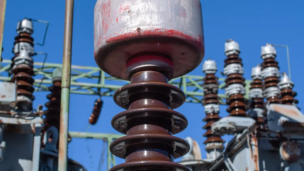
Old telecom power systems often depend on one rectifier shelf, one battery string, one distribution bus, and one system controller. This setup creates built-in weak spots. Even N+1 rectifier setups do not remove all shared risks. The shared bus and controller stay as common failure points that can take down the whole system.
Rectifier and Battery Strings as Single Points
A rectifier module failure can make the bus voltage drop. When one rectifier shelf powers the whole load, one module fault may overload the other units. This overload causes a cascading shutdown. The bus voltage falls below safe levels, and every device downstream loses power.
A battery string that cannot carry the load is another serious risk. Battery strings age at different rates. One weak cell can lower the whole string's capacity. During a utility outage, this weakened string cannot carry the load. The result is a full power loss to critical equipment.
Shared Bus and Controller Risks
A bus fault cuts power to every device downstream. This single non-redundant distribution path gives no other route for current to flow. One short circuit or loose connection on the main bus shuts down all connected loads at once.
A controller failure turns off monitoring and alarms. Operators lose sight of system status. They cannot spot rectifier faults, battery degradation, or voltage anomalies. This blindness turns a manageable issue into an undetected single point of failure. The system may fail without any warning.
Legacy architectures pile up risk in these shared components. True redundancy means removing every common control point. A tier 4 data center cannot put up with these weak spots. Financial data centers need a different approach.
Dual-Bus Architecture Creates Fault-Tolerant Infrastructure
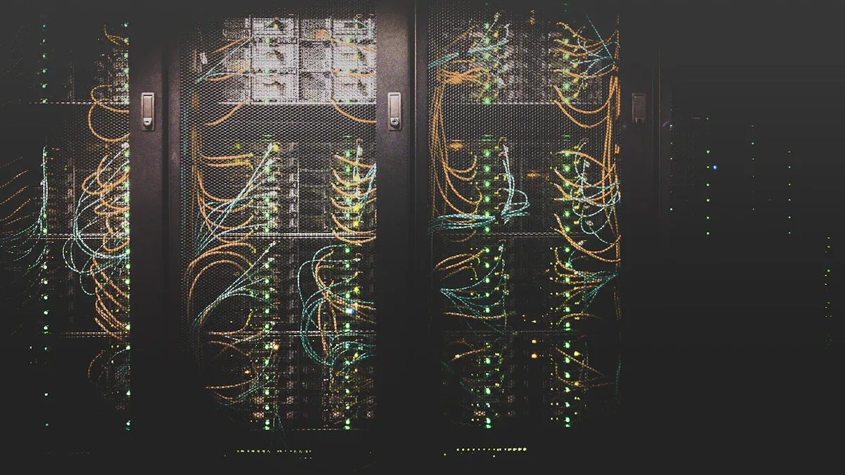
Dual-bus architecture uses two separate power buses. Each bus has its own rectifiers, battery banks, and distribution feeders. Automatic transfer switches or load-sharing mechanisms coordinate between them. This design creates fault-tolerant infrastructure by removing shared control points. Just duplicating components does not achieve this goal. True fault tolerance across the whole system requires removing every common failure point.
Fault Tolerant Infrastructure via Redundant DC Buses
Two buses run at the same time, and each carries the full load. This approach prevents single-bus overload problems. Equipment with dual power supplies connects to separate buses. Automatic load-balancing spreads demand evenly instead of depending on failover. Real-time monitoring spots imbalance and triggers automated fixes when tolerances are exceeded.
Running multiple power modules in parallel supports this architecture. Each module handles a share of the total load. Load-sharing controls and synchronization mechanisms keep operation balanced. Fault isolation stops cascading failures across modules. This supports N+1 or N+2 redundancy schemes.
Redundant distribution networks provide backup power paths. Dual-bus systems, ring configurations, or mesh networks create backup pathways for power distribution. Circuit breakers and transfer switches allow reconfiguration in response to faults. Critical loads can pull from multiple sources.
For converters with equal load current sharing, a straightforward and flexible droop management method is suggested to get rid of circulating current and bus voltage fluctuations. Three buck converters were controlled using adaptive droop control settings, which are monitored and modified live through the principal current sharing loops. This helps to minimize variations in load current sharing. To repair any voltage discrepancies brought on by the droop control technique, an outside addition voltage secondary loop is also employed to restore the proper voltage across the DC microgrid. 48 V is the ideal low-voltage LV DC distribution system voltage, and it is frequently used in the telecom sector.
This architecture delivers better reliability and uptime. Financial data centers gain backup pathways for power distribution that support continuous uptime goals.
ESTEL Telecom Power System for Dual-Bus Redundancy
The ESTEL Telecom Power System works as a practical building block for dual-bus deployment. It accepts a wide AC input voltage range from 90 to 280 Vac. This flexibility supports diverse power sources in financial data centers. An operating temperature range of -25°C to +55°C supports harsh deployment environments. The system installs on a standard 19-inch rack or inside a cabinet. Multiple communication ports enable smooth networking and integration. Output current reaches up to 90A.
These features support flexible, redundant deployment. Operators can pair two units to create independent buses. Each unit handles its share of the critical load. The system's communication ports allow separate monitoring paths for each bus. This separation removes shared control points that weaken redundancy.
Financial data centers need fault-tolerant system design at every level. The ESTEL Telecom Power System provides a dual-bus-ready foundation. It supports the redundancy required for a tier 4 data center. Operators achieve continuous uptime through deliberate architecture choices. Redundant UPS capacity and dual-powered equipment complement this approach. The combination creates a resilient power infrastructure.
Eliminating Failure Scenarios for Continuous Uptime
Dual-bus architecture changes what happens in every failure scenario that threatens legacy systems. If one bus has a fault, the other bus keeps the critical load powered. This design directly supports continuous uptime in financial data centers.
Rectifier, Battery, and Bus Fault Response
Think about the rectifier module failure we talked about earlier. In a legacy system, one module fault can overload the remaining units and make the bus voltage collapse. In a dual-bus design, each bus has its own rectifiers. A module failure on Bus A does not affect Bus B. The load shifts to the healthy bus on its own. Operators replace the failed module while the system keeps running normally.
The same idea applies to battery string failures. A weak cell in one string cannot drag down the whole system. Each bus keeps its own battery bank. If Bus A's battery string cannot carry the load during a utility outage, Bus B's battery bank makes up the difference. The critical load stays powered without any interruption.
Bus faults also lose their destructive power. A short circuit on one distribution bus no longer cuts power to every downstream device. The second bus provides redundant distribution paths for current to flow. Automatic transfer switches isolate the fault and reroute power. Financial data centers gain improved reliability and uptime through this separation.
Controller failures no longer blind operators. Dual-bus systems use separate monitoring paths for each bus. A controller fault on one side does not disable alarms on the other side. Operators keep full visibility of system status. They can spot rectifier faults, battery degradation, or voltage anomalies on either bus. This redundancy in control removes the shared point that turned manageable issues into undetected failures.
Maintenance and Upgrades Without Interruption
Routine maintenance no longer requires downtime. Battery replacement, rectifier swaps, and firmware upgrades can happen on one bus while the other bus carries the full load. Technicians work on Bus A while Bus B powers the critical equipment. This capability defines true fault-tolerant infrastructure.
Financial data centers need this level of concurrent maintainability. A tier 4 data center requires that any component can be serviced without affecting operations. Dual-bus architecture delivers this requirement. Operators schedule maintenance during business hours instead of waiting for maintenance windows. They avoid the risk of human error during rushed overnight work.
The design also supports capacity growth. Operators add rectifiers or battery strings to one bus while the other bus runs at full capacity. They upgrade firmware on one controller while the second controller maintains monitoring. Each bus operates as an independent power path. This separation ensures that no single maintenance event threatens continuous uptime.
Redundant UPS capacity complements this approach. Dual-powered equipment connects to both buses. Servers with dual power supplies draw from separate sources. The entire power chain stays dual-powered to ensure zero interruption. This architecture removes every shared component that could become a single point of failure.
Financial data centers achieve tier 4 reliability through deliberate design. Telecom power systems with dual-bus architecture provide the foundation. Operators who map every path from utility input to critical load will find no remaining shared component. The result is a power infrastructure that survives any single failure.
Best Practices for Tier 4 Data Center Power
A tier 4 data center needs more than just backup hardware. It needs power paths that are separate and can be worked on without shutting things down. The Uptime Institute says Tier IV means having more than one independent system that is physically apart. This physical separation stops one event from taking down both systems at the same time.
Tier IV – Fault-Tolerant Infrastructure is built with multiple independent, physically separate, and at the same time active paths. It can handle any fault: a serious outage or a burst pipe will not stop any processing power. This tier is usually used by global financial centers, defense networks, and critical hyperscale clouds.
Isolation, Monitoring, and Control Redundancy
Physical separation matters just as much as electrical separation. Operators must run independent distribution paths through separate conduits, rooms, or zones. This separation makes sure that a fire, flood, or human error in one area cannot reach the backup path.
Monitoring and control need the same care. Separate monitoring paths and backup controllers keep visibility working when one side fails. A tier 4 design uses constant fault-detection across every component. No shared control point can turn off alarms on both buses.
Requirement | Tier IV Specification |
|---|---|
Redundancy Model | 2N or 2N+1, with all paths active at the same time |
Fault Tolerance | Fully fault-tolerant; an unplanned failure of any single component or distribution path does not stop operations |
Distribution Paths | Both distribution paths are active at the same time; automatic failover with no manual switching needed |
Physical Separation | Physical separation to stop one failure from spreading to the backup system |
Additional Features | Constant fault-detection and monitoring; every component is duplicated |
Uptime | Continuous operation through fault tolerance (no single failure causes downtime) |
Capacity Planning and TIA-942 Alignment
Operators must size each bus so it can carry the full critical load by itself. This practice makes sure that losing one bus cannot overload the other. The remaining bus must handle 100 percent of demand without strain.
TIA-942 and Uptime Institute standards both require this capacity when a critical component is taken out of service. Backup UPS capacity and backup critical power sources support this goal. Dual-corded server loads connect to separate buses. This approach keeps critical IT equipment dual-powered across the whole chain.
Power Distribution Architecture: Tier 4 facilities need dual power paths with independent sources feeding each rack, making sure of redundancy from the utility feed through the UPS, generators, and PDUs to the server rack.
Concurrent Maintainability: Tier 3 and Tier 4 facilities support fully concurrent maintenance, meaning maintenance work such as cooling unit servicing and power distribution replacement can go on without stopping active operations.
The key is removing every shared control point. Fully backup systems with 2N or 2N+1 setups match this architecture. Backup data center power systems and high-availability data center electrical infrastructure deliver better reliability and uptime. Data center redundancy at every layer supports continuous uptime for financial operations.
Old telecom power systems break down because of single points of failure. Dual-bus architecture gets rid of them with two separate paths and backup parts, giving better reliability and uptime.
Operators must trace each path from the utility input to the critical load and find shared parts. Audit checks:
Follow the whole setup from utility feeds through switchgear, UPS, batteries, generators, transfer switches and distribution; compare it with the approved design.
Look at test failures, problems and response records, not just diagrams.
Confirm that generator, UPS, battery, transfer and failover tests used the intended path, including failed tests and delayed maintenance.
Continuous uptime and tier 4 data center reliability can still be reached. Dual-bus-ready equipment like ESTEL's Telecom Power System gives deliberate redundancy.
FAQ
What makes a single point of failure in a telecom power system?
A single point of failure is any part whose loss shuts down the whole system. One rectifier shelf, one battery string, one distribution bus, or one controller can cause this risk. Even N+1 rectifier setups still have shared bus and controller risks.
How is dual-bus architecture different from just duplicating components?
Dual-bus architecture runs two separate power paths at the same time. Each bus has its own rectifiers, battery banks, and distribution feeders. Just duplicating parts still leaves shared control points. True fault tolerance removes every common failure point across the whole system.
Can operators work on one bus without shutting down the other?
Yes. Battery replacement, rectifier swaps, and firmware upgrades can happen on one bus while the other bus carries the full load. This concurrent maintainability meets tier 4 data center requirements and avoids rushed overnight maintenance windows.
What capacity should each bus support in a tier 4 design?
Operators must size each bus to carry the full critical load by itself. Losing one bus cannot overload the other. TIA-942 and Uptime Institute standards require this capacity when a critical component is taken out of service.
How does the ESTEL Telecom Power System support dual-bus deployment?
The ESTEL Telecom Power System accepts 90 to 280 Vac input, operates from -25°C to +55°C, and installs on a standard 19-inch rack or inside a cabinet. It offers multiple communication ports and output current up to 90A.
See Also
Strategies for Guaranteeing Consistent Power Supply in Telecom Cabinets
Solar Energy Storage Power Solutions Designed for Telecom Cabinet Operations
Methods for Calculating Telecom Cabinet Power Systems and Battery Requirements
Grid-Tied Solar Inverter and Battery Systems for Telecom Cabinet Applications
Essential Insights into Key Features of Telecom Power Supply Systems
CALL US DIRECTLY
86-13752765943
3A-8, SHUIWAN 1979 SQUARE (PHASE II), NO.111, TAIZI ROAD,SHUIWAN COMMUNITY, ZHAOSHANG STREET, NANSHAN DISTRICT, SHENZHEN, GUANGDONG, CHINA
