Main Control Unit Hot Backup of Telecom Rectifier Systems: Dual Controllers Acting as Mutual Redundancy to Ensure Zero Downtime

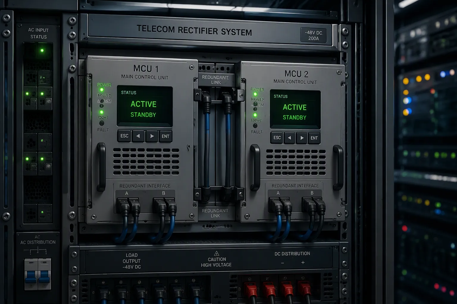
Dual main control units in hot backup act as mutual redundancy. This design removes the single point of failure and delivers zero downtime for your DC power plant. You already know the familiar problem. A controller failure can interrupt DC power to critical telecom loads even when your rectifier modules are fully redundant. The modules keep working, yet no unit manages them, so the load loses stable power. Understanding the mechanism, the benefits, and the practical design rules helps you evaluate or implement this approach in your Telecom Rectifier Systems. You gain a clear path to controller-level resilience.
Key Takeaways
Hot backup keeps two controllers active and synchronized. Each unit can take over instantly if the other fails.
Controller redundancy and N+1 module redundancy protect against different failures. You need both for full system resilience.
Dual controllers enable seamless switchover. The load sees no gap in DC power during a controller fault.
You can replace or update one controller while the other runs the site. This avoids downtime and maintenance windows.
Design your system with N+1 rectifier modules and dual controllers. Match the standby policy to your recovery needs.
Hot Backup in Telecom Rectifier Systems
Defining Hot Backup and Mutual Redundancy
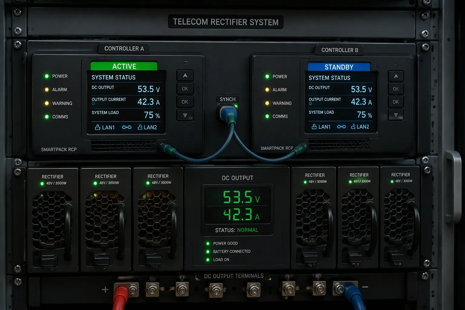
Hot backup means active redundancy. Both controllers run at the same time. One unit carries the active role. The other unit stays powered, synchronized, and ready. Mutual redundancy takes this idea one step further. Each controller watches the other. Either unit can take over the full workload at any moment. Neither unit is a dedicated spare. The standby unit does not sit idle. It tracks the active unit's state continuously. In a telecom rectifier context, this arrangement keeps the DC output stable through a controller fault. You gain a control layer that survives a fault without manual intervention. This design removes the single point of failure at the control level.
The active and standby roles differ in clear ways. The table below shows the division of labor in a mutual redundancy setup.
Component | Active Role | Standby Role |
|---|---|---|
Controller unit | Accepts client connections, evaluates health, decides to promote or remain active | Continuously synchronizes state from active; ready to take over |
Redundancy manager | Reports state = ACTIVE | Reports state = STANDBY |
Field device polling | Polls and writes to field devices | Behavior depends on standby activity level (cold or warm) |
Tag history and alarms | Authoritative source | Mirror (read-only for consumers) |
Client connections | Primary owner of sessions | Hot standby: connections migrate on failover |
A cold standby closes device connections. A warm standby stays connected, stops polling, and suppresses writes. The choice affects recovery speed.
The built-in Modbus TCP driver implements a cold standby by default. On the backup gateway, all device connections are closed. When the gateway is promoted to active, the driver reopens connections and resumes polling. Warm behavior is configurable per device connection.
This layered behavior lets you match the standby policy to the recovery speed your site needs. A cold standby favors simplicity and clean failover. A warm standby favors faster recovery because the connection already exists. You choose the policy that fits your site's tolerance for recovery time.
Controller Redundancy Versus N+1 Module Redundancy
N+1 rectifier redundancy protects against a single module outage. You add one extra rectifier module beyond the load requirement. If one module fails, the remaining units carry the load. This approach works well for module-level faults. It does not cover loss of the main control unit, the shelf backplane, or other single points of failure. You size the module count for the load plus one. The extra module absorbs the loss. This is the classic module-level protection scheme.
The SMU, or monitoring controller, plays a central role. It monitors voltage, current, system alarms, and battery status. It also coordinates the rectifier modules. A failed SMU leaves the modules without management. The load may lose stable power even though every module still works. Controller redundancy closes this gap. Two controllers in hot backup remove the single point of failure at the control layer. You keep N+1 module redundancy for the power stage and add mutual redundancy for the control stage. Together, these layers protect the whole Telecom Rectifier Systems architecture. Each layer covers a different failure mode, so neither one substitutes for the other. The control layer and the power layer fail in different ways. A module fault reduces capacity. A controller fault removes coordination. You need both layers for full resilience at the system level.
How Dual Controllers Ensure Zero Downtime
Mutual Monitoring and Fault Detection
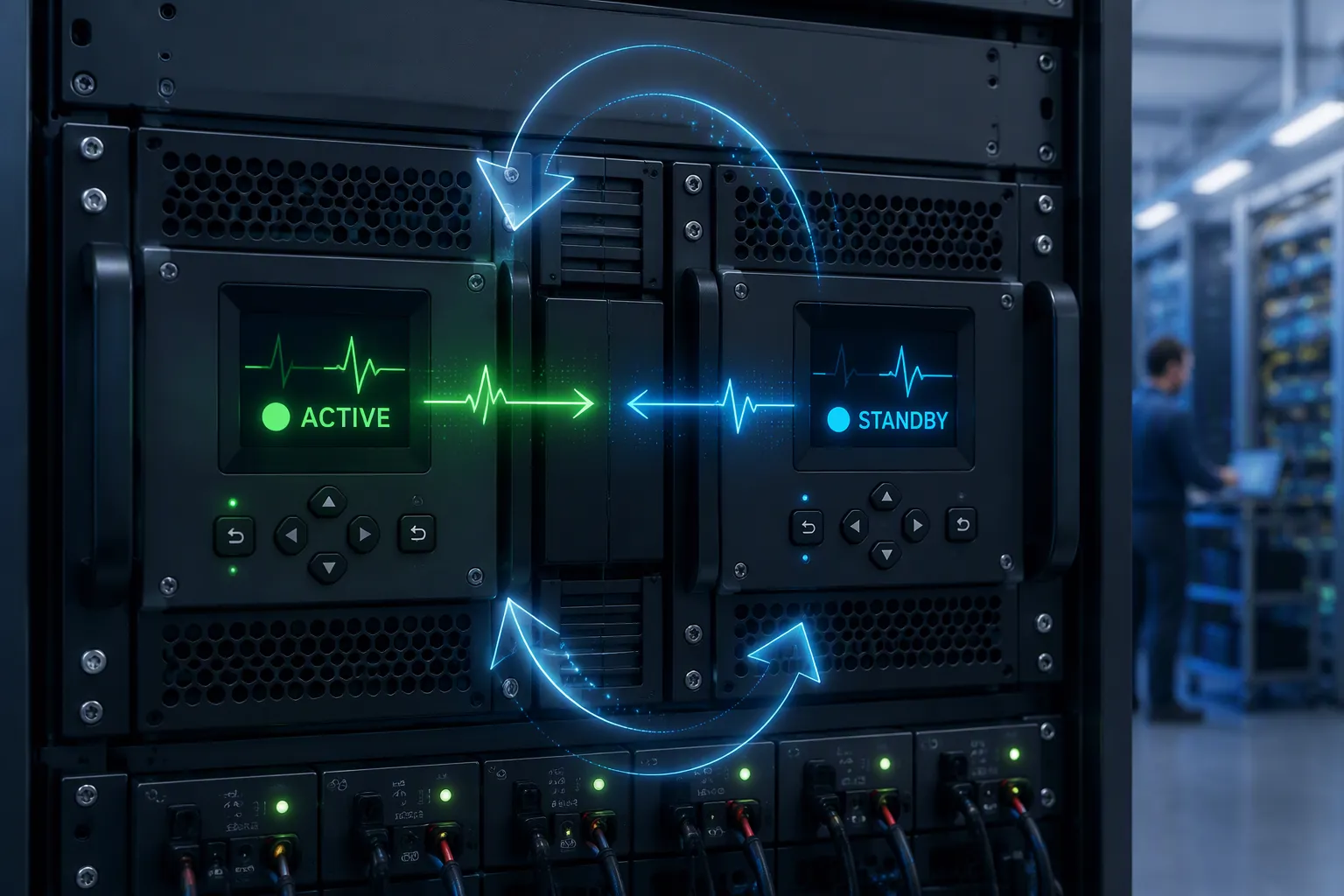
Each controller in a hot-backup pair watches the other unit continuously. The active unit sends a regular heartbeat signal to the standby unit. The standby unit sends its own heartbeat back. Both units track the timing of these signals. A missed heartbeat triggers a fault check. The standby unit then runs a deeper health test on the active unit. This test covers processor load, memory status, and communication links. If the active unit fails the test, the standby unit marks it as faulty. The standby unit also monitors its own health. A unit that detects its own degradation can hand over control voluntarily. This self-monitoring step prevents a slow failure from becoming a sudden outage. You gain two layers of detection: peer monitoring and self-diagnosis. Together, they catch both hard failures and soft degradation. The active unit also watches the standby unit. A failed standby unit raises an alarm, so you can replace it before the next fault event. This mutual watch keeps both units accountable at all times.
Data Synchronization and Seamless Switchover
The active unit holds the authoritative system state. This state includes voltage setpoints, current limits, alarm thresholds, and battery status records. The active unit pushes state updates to the standby unit on a fixed cycle. The standby unit applies each update to its own memory. It does not act on the data while it remains in standby mode. It only mirrors the state. This mirroring keeps the standby unit ready to assume control at any moment. The synchronization covers configuration data and live operating data. Configuration data changes rarely. Live data changes constantly. Both types must stay current for a clean handover.
Switchover follows a defined sequence. The standby unit detects the active unit fault. It confirms the fault through its health check. It then promotes itself to the active role. The promotion takes effect within one control cycle. The new active unit resumes polling and writing to field devices. Client connections migrate to the new active unit. The DC output of your Telecom Rectifier Systems stays stable through this transition. The load never sees a gap in control. A cold standby reopens device connections during promotion. A warm standby already holds those connections open, so it resumes polling faster. You choose the standby policy that matches your recovery time target. The switchover stays invisible to the load in both cases.
Benefits of Controller-Level Redundancy
Reliability, Maintenance, and Scalability
Controller-level redundancy changes how you maintain a live site. You can replace a faulty controller without cutting DC power to the load. The healthy unit keeps managing the rectifier modules during the swap. This removes the need for a maintenance window. You also gain freedom to update firmware on one unit while the other carries the active role. The standby unit takes over after the update, and you repeat the process on the second unit. Your maintenance schedule no longer competes with service continuity.
Scalability improves as well. You add rectifier modules to meet growing load demand. The control layer already tolerates a controller fault, so growth does not add a new single point of failure. A site that starts small can expand without redesigning its control architecture. The same mutual redundancy model serves a compact cabinet and a larger rack installation. You plan capacity growth around the power stage, not around the controller.
Operational and Cost Trade-Offs
A second controller adds hardware cost and rack space. You weigh that cost against the price of an outage. Critical telecom loads carry revenue and service obligations. A controller fault without backup can interrupt DC power to those loads. The added unit removes that exposure. You also reduce truck rolls for emergency repairs, because a failed controller no longer forces an immediate site visit.
The trade-off extends to power draw and configuration effort. Two controllers consume more energy than one, and you must configure synchronization and failover policies. These costs stay modest against the protection you gain. You match the standby policy to your recovery target, so you do not over-engineer a site with low traffic. A cold standby suits sites with relaxed recovery needs. A warm standby suits sites where fast takeover matters. This tiered approach keeps the cost proportional to the risk. You protect your Telecom Rectifier Systems at the control layer without overspending on every site.
Designing Telecom Rectifier Systems for Redundancy
Performance, Fit, and Compliance
You start the design with the power stage. Size the rectifier modules for the full load plus one spare unit. This N+1 arrangement covers a single module fault. Then add the control layer. Two controllers in hot backup remove the single point of failure at the monitoring level. Match the standby policy to your recovery target. A cold standby suits sites with relaxed recovery needs. A warm standby suits sites where fast takeover matters.
Check the application fit next. Confirm the input voltage matches your site supply. Verify the output voltage suits your load. Review the rack space against your cabinet layout. Confirm the operating temperature range covers your climate. Regulatory compliance follows the same discipline. Check that the system meets the safety and electromagnetic standards your market requires. Cost considerations close the review. Weigh the second controller against the cost of an outage. Keep the protection proportional to the risk at each site.
Implementation with ESTEL
The ESTEL Telecom Rectifier System gives you a platform built for this layered design. It delivers a DC48V output with efficiency above 96%. You choose an AC220V or 380VAC input option to match your site supply. The modular rack-mount design comes in 2U, 3U, and 6U configurations. Each unit fits a standard 19-inch rack, so integration into existing infrastructure stays straightforward.
The table below shows where each configuration fits best.
Configuration | Typical Fit |
|---|---|
2U | Compact sites with modest load demand |
3U | Mid-size installations that need room to grow |
6U | Larger sites with higher current demand |
Grounding protection through a copper bar and a flexible cable inlet design simplify installation. You pair the system with dual controllers in hot backup and gain mutual redundancy at the control layer. This combination protects both the power stage and the control stage of your Telecom Rectifier Systems.
Hot-backup dual controllers give you mutual redundancy at the control layer. This design removes the single point of failure and sustains zero downtime. Each unit monitors its partner, mirrors the active state, and takes over in a seamless switchover. You keep stable DC power through a controller fault, and you gain freedom to maintain or update one unit while the other runs the site.
Apply these practices to your own deployment. Size the power stage for N+1, then add the control layer on top. The ESTEL Telecom Rectifier System supports this layered approach with its DC48V output, modular rack-mount design, and 19-inch rack compatibility. Plan both layers together, and your site stays resilient as load demand grows.
FAQ
What makes hot backup different from simply adding a spare controller?
A spare controller sits idle until someone installs it. Hot backup keeps both units powered and synchronized at all times. Each unit watches the other and stands ready to take over. You gain automatic recovery instead of a manual swap.
Does controller redundancy replace N+1 rectifier redundancy?
No. The two layers cover different failure modes. N+1 protects against a single module outage. Dual controllers protect against loss of the monitoring unit. You need both layers for full system resilience.
How fast does the standby controller take over?
The standby unit promotes itself within one control cycle after it confirms a fault. A warm standby resumes polling faster because its device connections stay open. A cold standby reopens connections during promotion. The load sees no gap in control either way.
Can I update firmware without taking the site down?
Yes. Update one controller while the other carries the active role. The standby unit then takes over, and you repeat the process on the second unit. DC power to the load stays uninterrupted throughout.
Which ESTEL configuration suits a site that needs controller redundancy?
All ESTEL Telecom Rectifier System configurations support the layered design. Choose 2U for compact sites, 3U for mid-size installations, and 6U for higher current demand. Each unit delivers DC48V output, fits a standard 19-inch rack, and accepts AC220V or 380VAC input.
See Also
Grid-Tied Solar Inverter and Battery Setup for Telecom Cabinets
Ensuring Reliable Power Supply for Telecom Cabinet Operations
Calculation Methods for Telecom Cabinet Power Systems and Batteries
ESTEL Smart Microgrid Energy Storage System for Telecom Cabinets
Solar Energy Storage Power System for Telecom Cabinet Applications
CALL US DIRECTLY
86-13752765943
3A-8, SHUIWAN 1979 SQUARE (PHASE II), NO.111, TAIZI ROAD,SHUIWAN COMMUNITY, ZHAOSHANG STREET, NANSHAN DISTRICT, SHENZHEN, GUANGDONG, CHINA
