How Sleep Energy-Saving Mode in Telecom Rectifier Systems Automatically Sleeps Redundant Modules Under Light Load for Ultimate Power Saving


Sleep energy-saving mode answers a simple question: why keep every rectifier awake when the site does not need them? This function tracks site load continuously. When demand falls, it moves redundant modules into a low-power sleep state. Active units keep carrying the traffic, so reliability stays intact while rectifier conversion losses drop.
Most telecom rectifier systems are sized for peak demand. For long stretches, they run far below capacity, and each module sits outside its best efficiency band. That is where redundancy becomes a cost rather than a safeguard.
You will see how the mechanism works, what savings to expect, and how it compares with other techniques. ESTEL telecom rectifier systems serve as the practical reference throughout.
Key Takeaways
Sleep mode saves energy by putting extra rectifier modules to sleep when site power demand is low.
Active modules run more efficiently when they carry a larger share of the load.
The system keeps enough active modules to maintain n+1 redundancy and wakes sleeping modules when demand rises.
You can set sleep and wake thresholds to match each site's daily load pattern.
Monitoring module states and alarms helps you verify savings and maintain reliability.
Redundancy and Light-Load Waste
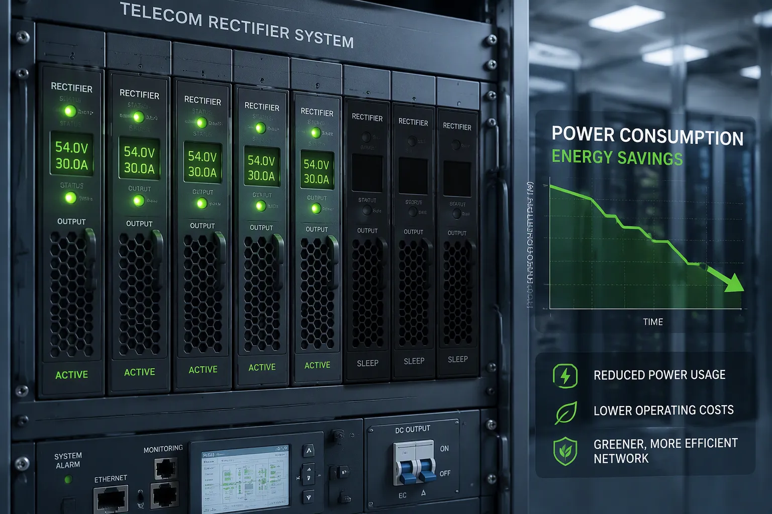
Why Telecom Rectifier Systems Carry Redundancy
A rectifier module converts AC power into the DC48V your telecom equipment needs. One module alone creates a single point of failure. A fault or a maintenance shutdown would cut power to the site. So designers add spare capacity. You will often see telecom rectifier systems built with one extra module beyond the peak demand, a pattern known as n+1 rectifier redundancy. Larger sites may carry several spares.
This design choice makes sense. Telecom sites must stay online through module failures, battery recharge cycles, and seasonal peaks. The spare capacity absorbs those events without service interruption. You get resilience, and you get it at the cost of installed capacity that sits idle most of the time.
The Efficiency Penalty at Light Load
Here is the trade-off. A site rarely draws peak power. Traffic drops at night. Cooler weather lowers cooling demand. Many remote sites run at a fraction of rated capacity for most of the day. Every module stays switched on during those hours, and each one operates far below its best efficiency point.
A rectifier module reaches peak efficiency near the upper part of its rated range. Push it down to a small share of that range, and conversion losses take a larger bite of every kilowatt delivered. Fixed overhead losses add to the problem. Control circuits, fans, and sensing hardware draw power whether the module carries a heavy load or a light one. Multiply that overhead across several modules, and the waste grows. This is the core weakness of part-load operation: the system burns energy on capacity nobody uses.
Hibernation offers a sensible answer for power modules. A sleeping module draws almost nothing, and it avoids the heat and stress of running in a poor efficiency band. The same logic applies to battery modules. Idle battery strings that stay in a standby state still see wear and small standing losses. Letting them rest cuts both. You save energy, and you extend service life, which lowers replacement costs over the years.
The concept is simple. Spare capacity protects you during peaks and faults. It does not need to stay awake during quiet hours. The next section shows how the system decides when to sleep a module and when to wake it.
How Sleep Mode Works in Telecom Rectifier Systems
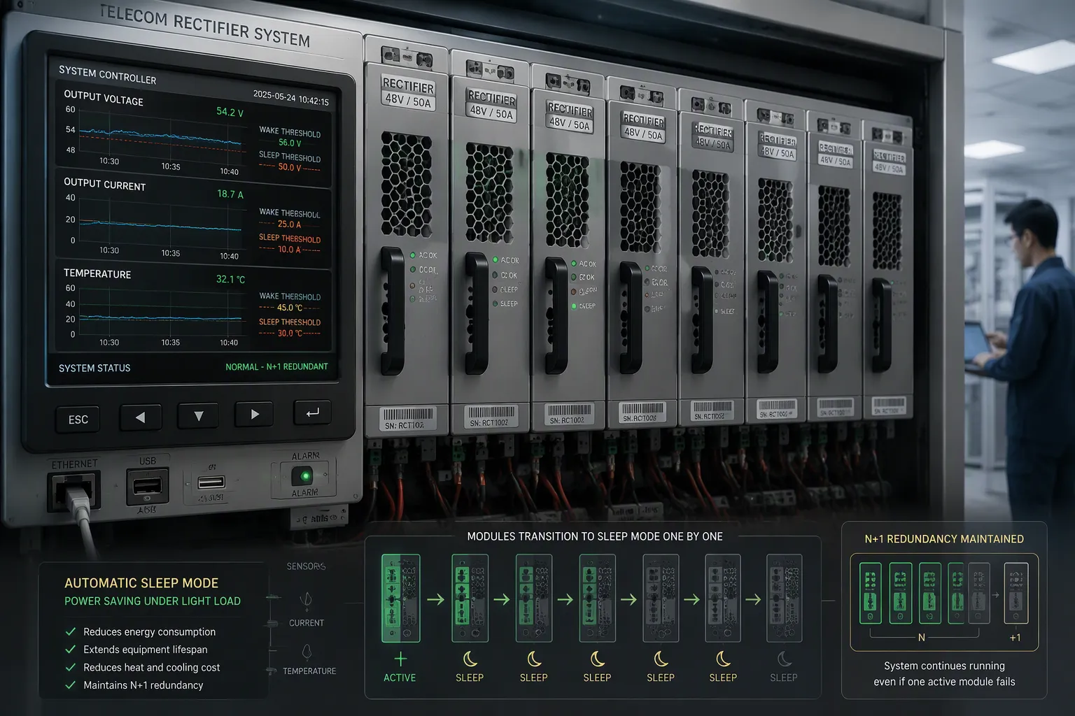
Load Detection and Thresholds
The system cannot sleep a module until it knows how much power the site actually draws. Built-in controllers and sensors track output voltage, current, temperature, and efficiency in real time. They also collect input voltage, output current, module temperature, and fan speed, and each reading carries a timestamp for time-series analysis. Sensors and gateways connect through SNMP for status polling and trap alerts, and through Modbus for serial or TCP register reads. Polling typically runs every 30–60 seconds, which is fast enough to capture load fluctuations before they become a problem.
You set the thresholds. A typical configuration defines a low-load point where the system begins to sleep spare modules, and a wake threshold where it brings them back. The gap between the two prevents rapid toggling. You can tune both values to match each site's daily load profile, so a quiet rural site and a busy urban site each get settings that fit their own pattern.
Control Logic for Sleep and Wake
The control logic applies a simple rule. When measured load stays below the sleep threshold for a set period, the controller hibernates redundant modules one by one. It keeps the minimum active modules needed to carry the current load plus the required redundancy. In sleep mode, most hardware inside a module disconnects from the clock and power supply. That step removes the fixed overhead losses that make light-load operation wasteful.
A rise in load triggers the reverse action. The controller wakes sleeping modules as demand climbs, and they return to service quickly. Immediate available redundancy is preserved throughout, because the logic never sleeps below the n+1 module redundancy floor. Some controllers also apply a rotation policy, so module sleep or rotation spreads operating hours across the fleet and no single unit carries all the wear.
ESTEL telecom rectifier systems show how these features fit together in practice. The modular rectifier shelf delivers a steady DC48V output and comes in 6U, 3U, and 2U rack-mount options. Efficiency exceeds 96%, and the modular design lets the controller manage each module's on/off/sleep state independently. That independence is what makes automatic sleep possible in a live telecom rectifier system.
Efficiency Gains and Savings
Quantified Power Savings
Sleep mode changes the math of part-load operation. High-efficiency rectifier series can exceed 97% efficiency across a 50%–90% load range. When the controller sleeps spare modules, the remaining active units carry a larger share of the output load. They move closer to that sweet spot instead of idling in a poor band. You gain twice: fewer modules burn fixed overhead, and each active module converts power at a better rate.
The savings scale with idle time. A site that runs light for many hours each day captures more benefit than one with a steady heavy draw. Pair the rectifier system with a Battery Energy Storage System (BESS) for backup. The BESS supplies critical loads that cannot be packetized, and it adds temporal flexibility. Sleep mode lowers demand on those same loads, so the two work as complements rather than rivals.
Configuration and Monitoring
Compatibility comes first. Check that your existing installation supports per-module sleep control before you enable the feature. Then set the threshold for each site's load profile. A rural site with long quiet nights needs different values than an urban site with a short lull.
Monitoring turns savings into evidence. Track each module's present/absent status, on/off/sleep state, output current, internal temperature, and fault flags. Define the minimum active modules, rotation policy, wake threshold, and wake response time at the controller. Configure alarms with timestamps and persistence delays, and retain the data as availability and maintenance evidence.
Monitoring Aspect | What to Capture |
|---|---|
Module state | On/off/sleep state, output current, temperature, fault flags |
Controller logic | Minimum active modules, wake threshold, wake response time |
Alarms | Normal ranges, severity, timestamps, latching rules |
KPI retention | Long-term records for availability and maintenance analysis |
This record shows how often sleeping modules wake and whether module redundancy stays intact. You can then tune settings and confirm that n+1 module redundancy with battery support holds through every transition.
Sleep Mode vs. Other Methods
Voltage Scaling vs. Modular Sleep
Voltage scaling lowers the output voltage of the rectifier system to trim losses at part load. The approach works well on sites with a stable, predictable draw. It changes the operating point of every module at once, so you get a system-wide effect from a single setting. Modular sleep takes a different route. It switches individual modules off, so the active units carry a higher share of the load and sit closer to peak efficiency.
The two methods differ in granularity. Voltage scaling suits smaller installations where per-module control adds little value. Modular sleep fits larger shelves with several modules, where module redundancy already exists and spare capacity can rest. On regulatory compliance, both stay within standard DC48V output tolerances when configured correctly. On cost, voltage scaling needs no extra hardware beyond the controller you already run. Modular sleep depends on per-module control, which modular platforms such as ESTEL telecom rectifier systems already provide.
Matching Method to Application
Choose the method that matches your site profile. A site with a flat, steady load gains little from sleeping modules, and voltage scaling may serve it better. A site with long quiet periods and a wide gap between peak and average demand captures more from module sharing/sleep, because idle hours are when the savings accumulate.
You can also combine the two. Voltage scaling handles fine adjustment across the whole system, and modular sleep removes entire units from service. Keep the redundancy floor in mind either way. Neither method should reduce your module redundancy below the n+1 level, and both must wake or restore full output before demand climbs. Test each option against your own load data, then pick the fit.
Sleep energy-saving mode delivers ultimate power saving through one simple habit. It watches site demand and puts spare modules to rest whenever the load drops. Active units then run near peak efficiency, and high-efficiency rectifier series can exceed 97% across a 50%–90% load range.
Reliability stays protected. The controller wakes sleeping units the moment demand climbs, and it never drops below the n+1 redundancy floor. You keep redundancy and resilience while you cut waste.
Start by evaluating your site load profiles. Then configure sleep and wake thresholds to match each pattern. ESTEL telecom rectifier systems offer a practical place to begin, with per-module control built into a modular telecom rectifier system.
FAQ
Does sleep mode weaken redundancy during a module fault?
No. The controller never sleeps below the n+1 redundancy floor. Active modules always cover the current load plus one spare. A fault triggers a wake command, and sleeping units return to service quickly.
Can small sites benefit from sleeping redundant modules?
Yes, when the site carries a spare module and runs light for long hours. A single-module site has nothing to sleep. Check your shelf configuration first, then compare peak and average demand.
How do I choose sleep and wake thresholds?
Match them to your site's daily load profile. Set the sleep point below your typical light-load level and the wake point above it. The gap between the two prevents rapid toggling.
Does sleep mode interfere with battery charging?
No. The controller keeps enough active capacity for the load and the recharge current. Battery support and n+1 module redundancy hold through every sleep and wake transition.
Can I enable sleep mode on an existing installation?
Only if your controller supports per-module sleep control. Verify that capability first, then confirm SNMP or Modbus monitoring so you can log each sleep and wake event.
See Also
Solar Energy Storage Power System Designed for Telecom Cabinets
Calculation Methods for Telecom Cabinet Power Systems and Batteries
Ensuring Reliable Power Supply for Telecom Cabinet Operations
Grid-Connected Solar Inverter and Battery System for Telecom Cabinets
ESTEL Smart Microgrid Integrated Energy Storage System for Telecom Cabinets
CALL US DIRECTLY
86-13752765943
3A-8, SHUIWAN 1979 SQUARE (PHASE II), NO.111, TAIZI ROAD,SHUIWAN COMMUNITY, ZHAOSHANG STREET, NANSHAN DISTRICT, SHENZHEN, GUANGDONG, CHINA
