How Telecom Rectifier Systems Automatically Sleep Redundant Modules

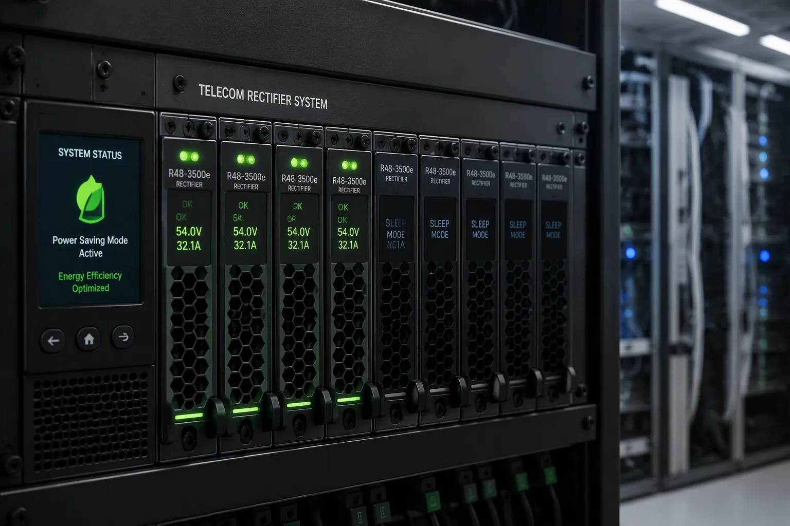
Picture a remote telecom site at 2 a.m. Traffic has dropped, and the site draws only a fraction of its rated capacity. Inside the cabinet, the telecom rectifier systems quietly place several redundant modules into sleep mode. The remaining units carry the load, and your network keeps running without a single dropped call. That is the dual promise of intelligent sleep logic: deep energy savings under light load, with high availability fully intact. ESTEL's Telecom Rectifier System applies exactly this logic to balance efficiency and reliability. So how do modules sleep automatically and still wake instantly when demand returns?
Key Takeaways
Telecom rectifier systems use extra modules for backup and put unused ones to sleep when power demand is low.
The system controller monitors load and wakes sleeping modules instantly when demand rises, keeping your network reliable.
Sleeping modules save energy, reduce cooling needs, and extend equipment life by reducing operating hours.
Battery hibernation rests surplus battery capacity to save wear while keeping enough backup power ready.
You can adjust sleep settings per site to balance energy savings with the level of redundancy you need.
Modular Architecture and Redundancy
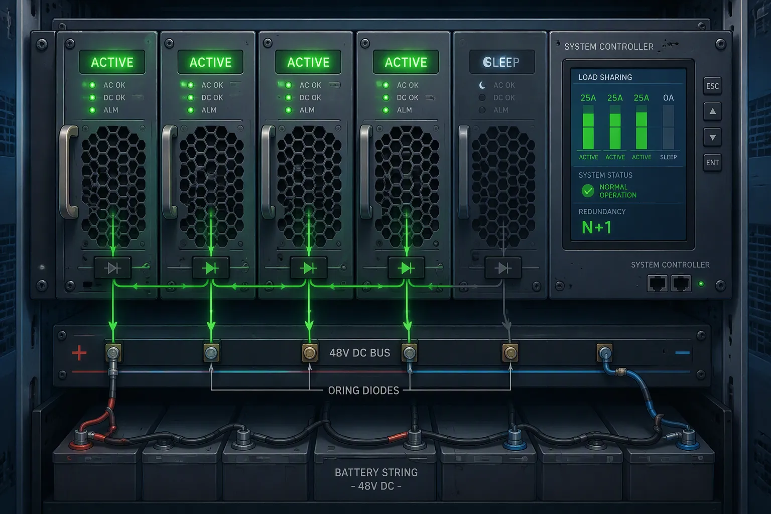
A telecom rectifier system turns AC input into a regulated 48V DC output and keeps the battery string charged. It does this with multiple modules that share the load, not one large converter. This modular layout is the foundation for everything that follows.
N+1 Redundancy in a Telecom Rectifier System
N+1 rectifier redundancy adds one extra module beyond the minimum needed to carry the load. Suppose your site needs 2 kW. You install three 1 kW modules. If one fails, the other two still deliver the full 2 kW, and service continues without downtime. Reliability data shows that key components inside rectifier modules, such as press-pack IGBT modules and metallized film capacitors, have measurable failure rates. That is why n+1 module redundancy matters: it absorbs a single failure without interrupting output.
Load sharing makes this work. Active current sharing distributes demand across the active modules. Output ORing diodes let you add or replace a module without interrupting the DC bus. A monitoring and control unit acts as the system brain. It measures bus voltage and current, manages battery charging, raises alarms, and reports to network operations centers. The table below summarizes the division of labor.
Component | Role in Load Sharing |
|---|---|
Parallel AC/DC rectifier modules | Share the load within their input, output, thermal, and current-sharing limits |
System controller | Coordinates operating states, output targets, module states, battery limits, alarms, and communications |
Active and Sleep States Explained
Each module can sit in one of two states. In the active state, it delivers power to the bus. In the sleep state, it shuts down its conversion stage and draws almost nothing. The remaining modules carry the load, so output never drops. You can later reactivate a sleeping unit without interrupting service. This is the heart of active-sleep mode.
The architecture must support this behavior. ESTEL's Telecom Rectifier System uses a modular rectifier shelf in 6U, 3U, and 2U rack-mount formats. It delivers DC48V output with efficiency above 96%. Hot-swappable rectifier modules slide in and out of the shelf, and the controller tracks each unit's state. That combination of module redundancy and controller oversight makes automatic sleeping practical. You gain redundancy for availability and efficiency for energy savings from the same design.
How Telecom Rectifier Systems Sleep Modules
Load-Based Activation and Parameters
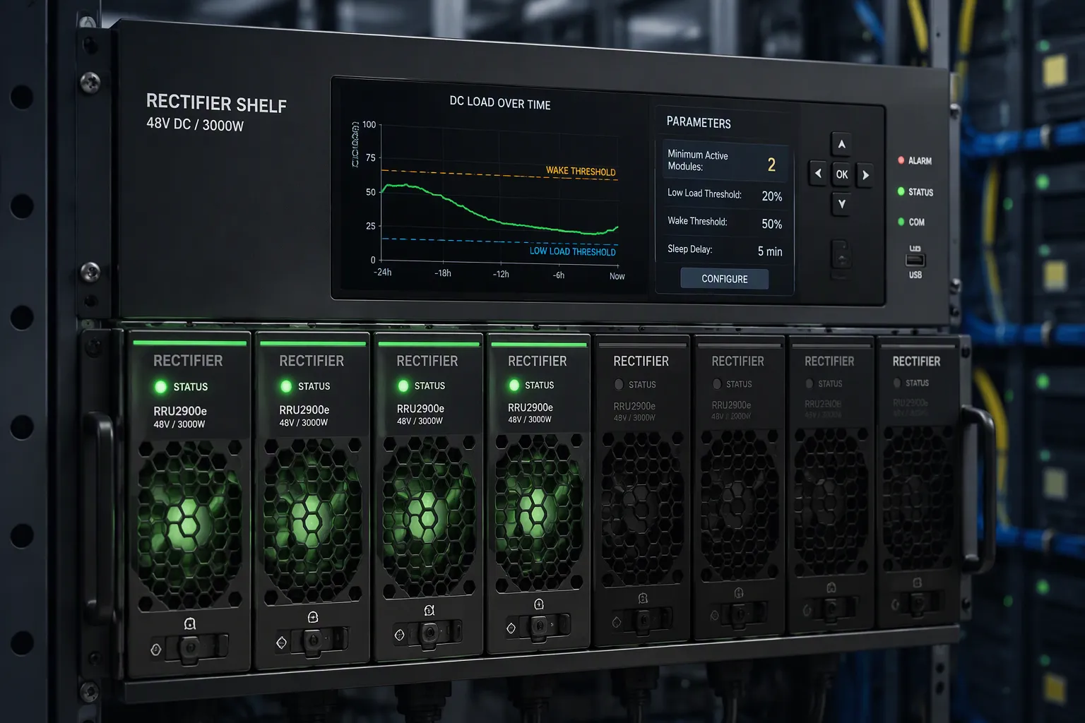
The sleep logic runs on a simple loop. The system controller measures the total DC load many times per second. It compares that reading against a set of configurable thresholds. When demand falls below the low-load threshold, the controller puts redundant modules to sleep one at a time. Each step is verified before the next begins. Output stays stable throughout.
Why does this save energy? A rectifier runs most efficiently near the middle of its range. At very low load, conversion losses take a larger share of the power drawn. Suppose four modules each run at 15 percent load. Each one wastes a disproportionate amount of energy. Now let two modules sleep and let the other two run at 30 percent each. The active units move closer to their optimal band of roughly 50 to 90 percent. Series such as SLIMLINE exceed 97 percent efficiency across that range. Fewer active modules at a better load point beat many modules idling at the bottom of their curve.
You control the behavior through several parameters. The table below shows the main ones.
Parameter | What It Governs |
|---|---|
Low-load threshold | The load level below which the controller begins module sleep |
Wake threshold | The load level that triggers reactivation of sleeping units |
Minimum active modules | The floor on active units, preserving module redundancy at all times |
Wake triggers | Load rise, module fault, or battery recharge demand |
Set the minimum active modules carefully. This value protects your redundancy. If you keep n+1 units awake at all times, you hold immediately available redundancy even in deep sleep mode.
Seamless Reactivation for Availability
Think of a multi-engine ship at cruising speed. The crew shuts down unused engines to save fuel. When the ship needs speed again, the idle engines restart and take their share of the drive. Nobody notices a change in course. A rectifier shelf behaves the same way. The moment load crosses the wake threshold, the controller restarts sleeping units. They rejoin the load-sharing bus within milliseconds. The ORing diodes and hot-swap design make this transition invisible to the DC bus.
This is where module sharing and sleep logic earn their keep. You get part-load operation savings without giving up availability. The system never sleeps below its minimum active count. A fault in an active unit also wakes a sleeping one at once. So the shelf always holds its designed redundancy level, whether the site draws full power or almost none.
Benefits of Sleeping Redundant Rectifier Modules
Energy and Cooling Savings
You gain real savings when the system puts redundant modules to sleep under light load. Fewer active units mean less conversion loss. The active units also run closer to their best efficiency point. A telecom rectifier system that keeps four modules awake at 15 percent load wastes more power than one that runs two modules at 30 percent each. The difference shows up directly on your electricity bill. Lower power draw also means less heat inside the cabinet. Your cooling equipment, whether air conditioners or heat exchangers, works less. That cuts cooling energy on top of the rectifier savings. The two effects compound at sites with tight thermal budgets.
Longer Equipment Life
Sleeping modules accumulate fewer operating hours. Electrolytic capacitors and fans inside a rectifier age mainly while the unit runs hot and delivers current. A module that rests for long stretches sees less thermal stress. Its components degrade more slowly. You get a longer service life from the same hardware. Maintenance intervals stretch out too, because fewer units wear at once. Field visits for module replacement drop, and so does the cost of spare parts. These benefits come from intelligent sleep logic, not from running equipment harder. Always-on configurations still suit sites where every module must stay warm and ready for instant full output. Sleep mode simply adds another option for sites with predictable light-load periods.
Battery Hibernation for Extra Savings
Coordinating Rectifier and Battery Sleep
Battery modules age even when they sit idle. A battery held at a high state of charge for long periods loses capacity faster than one kept in a calmer resting state. Hibernation addresses this. The system lets selected battery modules rest instead of holding them at full readiness around the clock. You reduce wear on the cells and stretch the working life of the string. For BESS-backed telecom sites, this matters twice over. The battery bank is often the most expensive asset in the cabinet, and every year you add to its service life lowers your cost per site.
The coordination step is what makes hibernation safe. The system controller watches the DC bus and the battery state together. It keeps enough battery capacity awake to meet your backup requirement at all times. Only the surplus capacity enters hibernation. When the bus needs support, the controller wakes the resting modules and returns them to service. You gain idle-time savings without weakening backup readiness.
Preserving Backup Readiness
Rectifier sleep mode and battery hibernation work as one plan, not two separate features. The controller sets a minimum active module count for the rectifier shelf, so the DC bus always has live power. It sets a parallel floor for the battery bank, so backup capacity never drops below your design target. Both floors stay under your control. You decide how much redundancy to hold awake and how much capacity to rest.
This layered approach protects availability at every step. A load rise wakes sleeping rectifier modules. A discharge event wakes hibernating battery modules. The two actions follow the same logic and the same controller. You get maximum idle-time savings while the site keeps its full backup capability. That balance of energy savings and reliability is the real payoff of coordinated sleep.
Implementation Considerations
Balancing Availability and Energy Goals
You face a trade-off when you enable sleep mode. More sleeping units save more energy, yet they leave less spare capacity awake. Start with your site's availability target. A critical hub may need full n+1 module redundancy awake at all times. A remote site with predictable light-load hours can safely rest more units. The feature is configurable per site, and you can disable it entirely where conditions demand.
Weigh each site on its own merits. Check the load profile, the battery backup requirement, and the maintenance response time. Sites that are hard to reach justify keeping more redundancy awake. Sites with steady traffic and quick service access can lean toward savings. Document your choice for each site, so future teams understand the reasoning.
Tuning Thresholds for Total Cost of Ownership
Threshold tuning drives your total cost of ownership. Set the low-load threshold too high, and modules sleep during busy periods, which wastes the savings. Set it too low, and they rarely sleep at all. Match the wake threshold to your measured load swings, and keep a sensible gap between the two values to prevent rapid cycling.
The minimum active module count deserves equal care. This setting protects your redundancy while you capture efficiency gains. A higher floor costs a little energy. A lower floor saves more but trims your safety margin. Test a few settings against real site data, then lock in the values that balance both goals. ESTEL's Telecom Rectifier System supports this tuning through its controller and monitoring functions, including maximum energy management functionality and maximum energy management function options. The modular shelf design fits diverse outdoor sites, and its efficiency above 96% rewards careful threshold work with measurable power savings.
Under light load, telecom rectifier systems handle efficiency automatically. The controller puts redundant modules to sleep and keeps only the minimum active. The rest run near their best efficiency point, so every watt of power counts.
Intelligent reactivation protects your redundancy at every moment. A rising demand wakes sleeping units within milliseconds, and the shelf keeps its designed redundancy intact. You gain energy, cooling, and equipment-life savings, and battery hibernation adds further savings on top. Review your own traffic profiles and tune the thresholds to your availability and TCO goals. ESTEL delivers intelligent, efficient power solutions, and the company pairs that power intelligence with rugged outdoor cabinets for diverse sites.
FAQ
How does a rectifier module enter sleep mode?
The system controller measures the total DC load continuously. When demand drops below your configured low-load threshold, the controller shuts down the conversion stage of redundant modules one at a time. The remaining active units carry the load, and the controller verifies stable output before each next step.
Will sleeping modules interrupt power to my site?
No. The remaining active modules carry the full load, and the controller never sleeps below your minimum active module count. Output ORing diodes and hot-swap design keep the DC bus stable. A load rise or an active module fault wakes a sleeping unit within milliseconds.
Which parameters should I tune first?
Start with the low-load threshold and the wake threshold. Keep a sensible gap between them to prevent rapid cycling. Then set the minimum active module count to protect your redundancy. Test a few settings against real site data before you lock in values.
Does sleep mode suit every site?
Not always. Critical hubs may need full n+1 redundancy awake at all times. Remote sites with predictable light-load hours can rest more units. The feature is configurable per site, and you can disable it where conditions demand. Match the setting to each site's load profile and service access.
How does battery hibernation fit in?
The controller keeps enough battery capacity awake to meet your backup target. Only surplus capacity rests. A discharge event wakes the hibernating modules at once. Rectifier sleep and battery hibernation follow the same logic, so you capture idle-time savings without weakening backup readiness. This coordinated approach delivers real power savings alongside full availability.
See Also
Ensuring Reliable Power Supply for Telecom Cabinet Operations
Calculation Methods for Telecom Cabinet Power Systems and Batteries
Grid-Connected Photovoltaic Inverter and Battery System for Telecom Cabinets
Photovoltaic Energy Storage Power System for Telecom Cabinet Applications
CALL US DIRECTLY
86-13752765943
3A-8, SHUIWAN 1979 SQUARE (PHASE II), NO.111, TAIZI ROAD,SHUIWAN COMMUNITY, ZHAOSHANG STREET, NANSHAN DISTRICT, SHENZHEN, GUANGDONG, CHINA
