How to Implement Comprehensive Over/Under-Voltage Protection for 48V Telecom Systems


Implement comprehensive protection for 48v telecom systems in five steps. First, define your voltage thresholds. Second, select coordinated clamping and disconnect devices. Third, add self-healing short-circuit recovery. Fourth, build automated diagnostics. Fifth, gate every restart on verified fault clearance.
The stakes are practical. A voltage excursion can damage rectifiers and batteries, trigger outages, and send a technician to a remote site. A telecom rectifier system must guard against these events, as the ET48300-004 does with input over/under-voltage and short-circuit protection. This post walks through each step in order as a design checklist, so you can deliver comprehensive protection against over-current, over-temperature, over-voltage and short circuits.
Key Takeaways
Define voltage thresholds using standards like ETSI or ITU-T to set normal, transient, and sustained bands.
Choose coordinated protection devices: TVS diodes and varistors for fast clamps, crowbars and disconnects for sustained faults.
Use an efuse for self-healing short-circuit recovery and automated diagnostics to log faults.
Gate auto-restart on verified fault clearance to prevent repeated cycling against hard faults.
Test the entire protection chain on the bench and in the field to ensure reliable performance.
Voltage Limits for 48V Telecom Systems
Over/Under-Voltage Windows
Start by writing down the acceptable operating window for your plant. A nominal 48V rail rarely sits at exactly 48v. Float charging, equalize cycles, and load steps all move the bus. Define a normal band, a transient band, and a sustained-deviation band for each one.
Treat transient and sustained deviations differently. A short spike during a lightning strike or a load dump needs fast clamping. A slow drift outside the band points to a rectifier fault or a failing battery string. Set a ride-through time for transients and a separate trip time for sustained excursions. Document both in your protection specification.
Standards and Compliance
Anchor your thresholds in published standards. ETSI and ITU-T documents define DC power interfaces for telecom equipment. Telcordia requirements cover central-office DC plants. These standards give you voltage ranges, ripple limits, and immunity test levels. Pull the clauses that apply to your market and record them next to each threshold.
Compliance is a design input, not an afterthought. Check that your protection thresholds sit inside the immunity envelope your equipment must survive. Verify that 48 v dc-dc conversion stages tolerate the same window. Confirm your design handles over voltage and over temperature protection together, since heat often follows a sustained overvoltage event. Build a short compliance checklist and sign it off before you freeze the schematic.
Selecting Circuit Protection Devices
TVS Diodes and Varistors
Clamping devices absorb the first hit. A TVS diode reacts in picoseconds and holds a precise clamping voltage, according to HJL Elec. A varistor handles large surge energy with a broader tolerance and a slower response in the nanosecond to microsecond range. The same source notes that varistors may degrade after repeated surges, while TVS diodes stay stable.
Feature | TVS Diode | Varistor |
|---|---|---|
Response time | Picoseconds | Nanoseconds to microseconds |
Surge energy | High, for transient spikes | High, for power surge absorption |
Voltage precision | Precise clamping | Broader tolerance |
Longevity | Stable under repeated surges | May degrade after repeated surges |
Best fit | Boards, communication, sensitive electronics | Power supplies, large industrial equipment |
Place a TVS diode at the sensitive board input. Use a varistor at the power supply front end, where bulk surge energy arrives. Many telecom power systems combine both stages for layered defense.
Crowbar Circuits and Disconnects
A crowbar circuit deliberately shorts the rail to force a breaker or fuse open. This approach suits sustained overvoltage events that a clamp cannot absorb. A disconnect element then isolates the faulted branch. Size the crowbar to survive the let-through energy until the disconnect clears the line.
Match each element to its job. Clamps handle short-circuit and overcurrent transients. Crowbars and disconnects handle sustained faults. An electronic fuse adds resettable over current protection and adjustable overcurrent and overvoltage protection. ESTEL's Telecom Power System accepts 90–300 Vac input and uses natural cooling, which supports robust front-end protection in cabinet installations.
Self-Healing Short Circuits with Efuse and Diagnostics
Resettable Efuse and Current Limiting
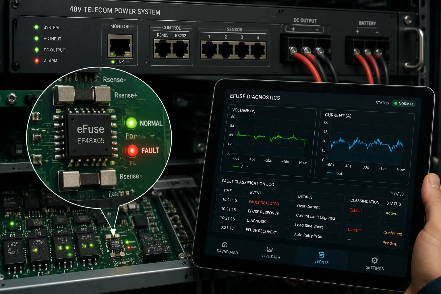
An electronic fuse changes how your plant handles a short circuit. A conventional fuse opens once and stays open. An efuse senses current in real time and limits it before damage spreads. When a short circuit occurs, the efuse enters a current-limiting mode. It holds the output over-current at a safe level, then waits for the fault to clear. This behavior delivers over current protection with auto recovery, so the rail returns to service without a site visit.
You configure two thresholds on the efuse. The first sets over current protection for normal load surges. The second sets output over-current trip for a hard short circuit. A current-limiting loop then caps the output over-current/short circuit energy. The efuse also watches output over-voltage and output over-current conditions together. Pair this with over voltage and over temperature protection, and the efuse covers the full fault envelope. The result is self-healing auto-retry modes that recover automatically once the short circuits clear.
Automated Fault Detection and Logging
Diagnostics turn a fault into data. Start with voltage monitoring on every rail. The controller samples the bus and compares each reading against your thresholds. Next comes fault classification. The logic separates an overvoltage event from an overcurrent event, and a short circuit from a slow drift. Each class gets its own response and its own log entry.
Event logging records the timestamp, the fault class, and the measured value. This record supports fault response and recovery analysis later. The self-healing loop then checks whether the fault is resolved. It re-measures the rail, confirms the short circuits are gone, and only then allows a retry. This closed loop delivers fault recovery without manual intervention.
ESTEL's Telecom Power System includes multiple communication ports. These ports support integrated diagnostic telemetry and networked remote monitoring. You can pull integrated telemetry and diagnostics into your site management system and watch the efuse state from a distance. That visibility shortens fault response and recovery time across a whole cabinet fleet.
Safe Auto-Restart and System Integration
Fault-Clearance Verification
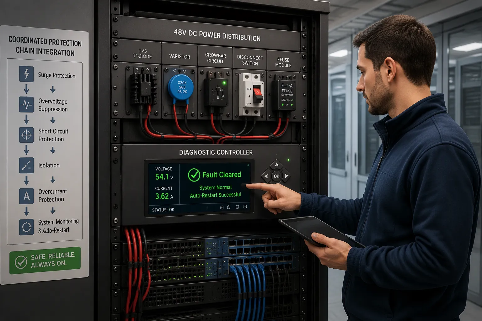
A safe automatic restart follows a fixed sequence. You program the controller to run these steps in order, and you never skip one.
Confirm fault clearance. The controller re-measures the rail and checks that the short-circuit condition is gone. It also confirms the efuse has left current-limiting mode.
Verify voltage is within limits. The bus must sit inside your normal band, not the transient band. A reading outside the window blocks the restart.
Re-energize the branch. Only after both checks pass does the controller close the disconnect and restore output.
Define stop conditions before you enable auto-retry. A repeated fault within a set window should lock out the branch and raise an alarm. An overvoltage reading during the check should also halt the sequence. These stop conditions prevent a self-healing loop from cycling endlessly against a hard fault.
Coordinating the Protection Chain
Each device in the chain has one job, and the chain works only when the jobs line up. The TVS diode and varistor clamp fast transients at the front end. The crowbar and disconnect handle sustained overvoltage and isolate the faulted branch. The efuse provides over current protection with auto recovery for short circuits on the load side. The diagnostic controller watches all of them and decides when a restart is safe.
Set the thresholds so each stage hands off cleanly to the next. The clamp voltage must sit above your normal band and below the equipment survival limit. The efuse trip point must sit above normal load surges and below the wiring rating. The disconnect must clear before the crowbar overheats. Document these margins in one table and review them together, because a change to one threshold shifts the others.
ESTEL's Telecom Power System fits this chain as a rack-mount, cabinet-ready platform. It installs on a standard 19-inch rack or inside a cabinet, so it integrates with existing setups without a redesign. Its multiple communication ports carry diagnostic data to your site management system. That link lets you monitor fault recovery and adjust configurable auto-retry modes from a distance. The platform supports 48v telecom systems that need coordinated output over-voltage and output over-current protection in one enclosure.
Treat the whole chain as one system during design review. Walk through a fault scenario for each device and confirm the next stage picks up where the last one stops. This discipline turns separate parts into a single protective layer.
Testing for High Reliability
Bench and Field Validation
Prove the design on the bench before you trust it in the field. Build a test rig that can inject both overvoltage and undervoltage at the input. Drive the rail above your normal band and hold it there. Confirm the clamp responds first and the disconnect opens only when the excursion persists. Repeat the test at the low end and watch for a clean trip.
Next, create a controlled short-circuit on the load side. Use a switchable load bank to pull the rail into a hard fault. Verify that the efuse limits current within its configured window. Check that the efuse recovers after you remove the fault. Run the same scenario in the field on a live cabinet, with the load disconnected first. Field tests confirm that cabinet wiring and grounding do not change the response you measured on the bench.
Verifying Diagnostics and Restart
Validate diagnostic accuracy against known faults. Inject a defined overvoltage and confirm the log records the correct class, timestamp, and measured value. Repeat for an overcurrent event and for short circuits. Compare each log entry to your test instrument readings. A mismatch means the sampling or classification logic needs adjustment.
Then test the restart sequence under real fault conditions. Force a fault, clear it, and confirm the controller verifies clearance before it re-energizes. Introduce a lingering fault and check that the stop condition blocks the auto-retry. Confirm the efuse stays in current-limiting mode until the fault clears. Run the cycle several times to confirm repeatable behavior.
These tests build self-healing system reliability you can document. Record every result against your compliance checklist and the ETSI, ITU-T, or Telcordia clauses you cited earlier. A protection chain that passes bench and field validation, logs accurately, and restarts safely gives you confidence in long-term site performance.
You now have a six-step roadmap. Apply it in order:
Set thresholds against ETSI, ITU-T, or Telcordia clauses.
Select and configure clamps, crowbars, and disconnects.
Add efuse recovery and automated diagnostics.
Gate auto-restart on verified fault clearance.
Coordinate the chain as one system.
Validate on the bench and in the field.
Treat this as a checklist for your own 48v telecom systems. Confirm each step before you move to the next. The efuse stage deserves extra attention, since it drives self-healing behavior. ESTEL's Telecom Power System supports the build with a rack-mount, cabinet-ready platform and multiple communication ports.
FAQ
What voltage window should I set for a 48V plant?
Set a normal band, a transient band, and a sustained-deviation band. Anchor each one in the ETSI, ITU-T, or Telcordia clauses that apply to your market. Give transients a ride-through time and sustained excursions a separate trip time.
Do I need both a clamp and a crowbar?
Yes, when your fault envelope includes fast spikes and sustained overvoltage. A TVS diode or varistor clamps the fast event. A crowbar with a disconnect isolates the sustained one. Size each stage so it hands off cleanly to the next.
How does the system recover from a short circuit without a site visit?
A resettable efuse limits current during the fault and waits for it to clear. The controller then re-measures the rail and confirms the fault is gone. Only then does it allow a retry, so the branch returns to service automatically.
What stops an auto-restart from cycling against a hard fault?
Define stop conditions before you enable auto-retry. A repeated fault inside a set window should lock out the branch and raise an alarm. An out-of-window voltage reading during the clearance check should also halt the sequence.
See Also
Ensuring Reliable Power Supply for Telecom Cabinets
How ESTEL Maintains Proper Voltage for Communication Cabinets
Solar Energy Storage Power System for Telecom Cabinets
Calculation Methods for Telecom Cabinet Power Systems and Batteries
Grid-Connected Solar Inverter and Battery System for Telecom Cabinets
CALL US DIRECTLY
86-13752765943
3A-8, SHUIWAN 1979 SQUARE (PHASE II), NO.111, TAIZI ROAD,SHUIWAN COMMUNITY, ZHAOSHANG STREET, NANSHAN DISTRICT, SHENZHEN, GUANGDONG, CHINA
