Integrated Power Systems and DL/T1074-2019 Compliance in Power Automation

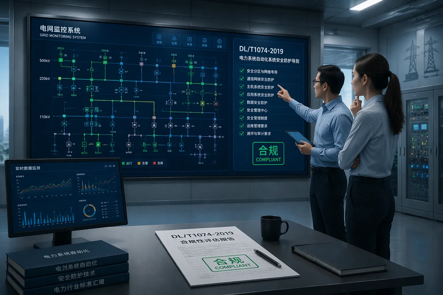
Full compliance with DL/T1074-2019 demands a systematic approach. You must address system architecture, equipment selection, protection and control, testing, and documentation together. Off-grid scenarios need special provisions on top of these basics.
This guide gives you a practical path. You will learn how to read the standard's requirements, design automation systems that meet them, and adapt those designs for isolated operation. Certification then becomes a manageable process, not a guessing game.
The sections ahead cover the standard's requirements, automation design strategies, off-grid specifics, an implementation roadmap, and common pitfalls. Each part builds on the last, so you can move from understanding to action. Integrated Power Systems deserve this end-to-end treatment from the start.
Key Takeaways
DL/T1074-2019 compliance covers five areas: architecture, equipment, protection and control, testing, and documentation. Address all five together for success.
Freeze your system architecture early. Late changes cause delays and cost more.
Rerun protection coordination studies after every source or load change. Keep settings up to date.
Keep a complete, versioned documentation package. Reviewers need it for certification.
Test protection and control logic on the bench first. Fix errors early to save time and money.
DL/T1074-2019 Requirements for Integrated Power Systems
Key Clauses and Practical Implications
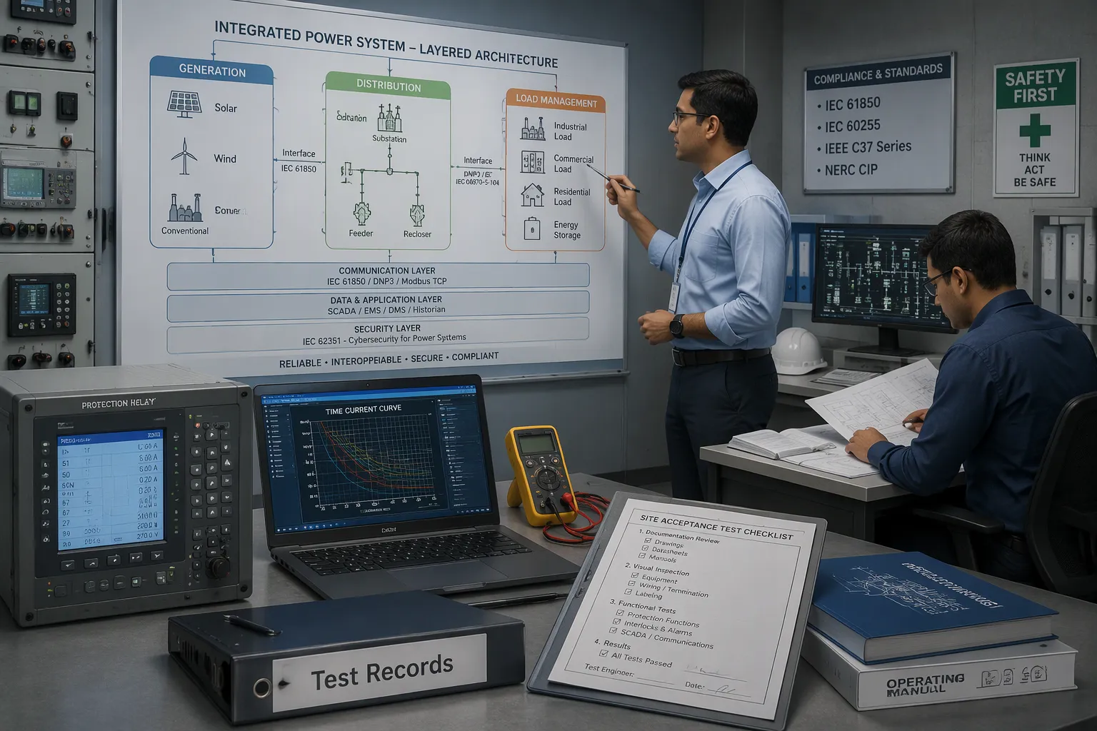
DL/T1074-2019 sets the technical baseline for power automation in integrated power systems. The standard covers five main areas. First, it addresses system architecture. You must define how generation, distribution, and load connect as one coordinated unit. Second, it covers equipment selection. Every device must match the voltage, current, and environmental conditions of your site. Third, the standard governs protection and control. Your system needs coordinated protection schemes and reliable control logic. Fourth, it requires testing. You must prove performance through type tests and site acceptance tests. Fifth, it demands documentation. Design drawings, test records, and operating manuals must form a complete, traceable package.
These requirements carry direct practical weight. A project manager can treat each area as a work package with clear deliverables. An engineer can treat each area as a design checklist. The standard does not ask for perfection in one area. It asks for consistency across all five. A weak link in documentation can delay certification even when the hardware performs well.
How the Standard Shapes System Architecture
The standard pushes you toward a layered architecture. You separate power generation, power distribution, and load management into distinct functional blocks. Each block has defined interfaces. This separation makes protection coordination easier. It also simplifies testing, because you can verify each block on its own before full integration.
Architecture decisions flow from the standard's emphasis on coordination. You must size your power sources to handle the full load profile, including peak demand and transient conditions. You must route distribution paths so that a single fault cannot cascade across the whole system. You must place monitoring points where operators need visibility, not just where wiring is convenient.
The standard also shapes redundancy choices. For critical loads, you need backup paths and automatic transfer logic. The architecture must support these functions without creating new failure modes. A simple example: if you add a backup rectifier bank, your protection settings must account for the changed fault current profile.
For engineers, the message is clear. Design the architecture around function, not around equipment convenience. For project managers, the message is equally clear. Freeze the architecture early. Late changes ripple through protection settings, test plans, and documentation, and each ripple costs time.
These requirements apply to every integrated power system, whether grid-tied or isolated. The next sections show how to turn them into equipment choices and control designs.
Designing Power Automation Systems for Compliance
Equipment Selection and Protection Coordination
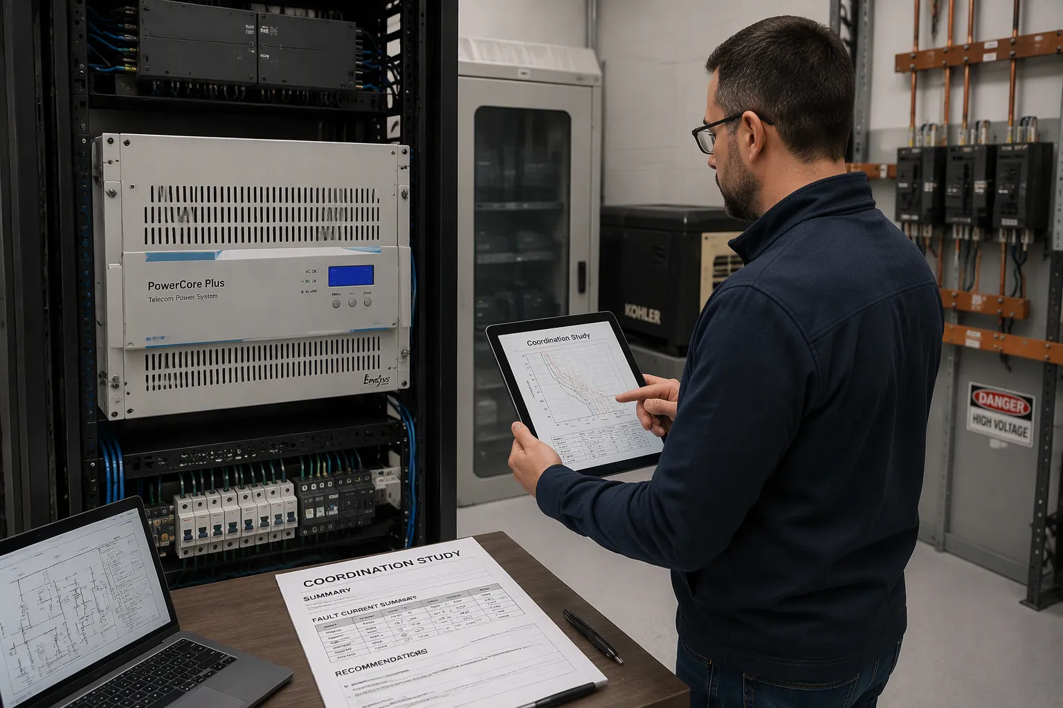
Equipment selection starts with the site conditions, not the catalog. You must match every device to the voltage window, the load profile, and the thermal environment of your installation. A wide input tolerance buys you margin against weak grids and generator transients. ESTEL's Telecom Power System, for example, accepts 90–300 Vac input and delivers 20–36 VDC output at up to 150 A. That range suits sites where supply quality varies through the day. The unit uses natural cooling, so it needs no fan maintenance and no extra cooling equipment. It mounts on a standard 19-inch rack or inside a cabinet, and it weighs no more than 10 kg without the rectifier module. These traits fit remote and space-limited sites well. Other topologies, such as forced-air cooled shelves or modular chassis systems, fit high-density central offices better. Choose by fit, not by habit. Check the environmental ratings against the site as well. Dust, humidity, and temperature swings shorten the life of any device that is under-rated for its location.
Protection coordination follows equipment choice. You must set breaker curves and fuse ratings so the nearest device clears a fault first. Start with the fault current profile at each bus. Then verify that upstream devices hold long enough for downstream devices to trip. Check the settings against the backup source too. A generator or battery bank changes the fault current, and stale settings can defeat selectivity. Run the study again whenever you add a load or change a source. Coordination is a living document, not a one-time calculation. The standard expects this discipline across the whole system. Document every setting in a coordination study. That study becomes a certification artifact later, and reviewers will ask for it.
Control, Communication, and Monitoring Integration
Control logic turns your architecture into a working system. You need automatic transfer, load shedding, and alarm handling that respond within the time your loads can tolerate. Write the logic as a clear sequence of states and transitions. Define fail-safe states for every output. If a controller loses communication, the system should default to a safe condition, not an undefined one. Test each step in isolation before you connect the full system. A logic error found on the bench costs hours. The same error found on site costs days.
Communication ties the pieces together. Multiple communication ports on the power system let you link rectifiers, batteries, and site monitors into one network. ESTEL's Telecom Power System includes several ports for networking and integration. Use them to push alarms and measurements to a central platform. Keep protocols consistent across vendors. Label every port and cable in the rack. A mixed-protocol site slows every future upgrade and complicates remote diagnostics.
Monitoring deserves the same rigor as protection. Define which values you log, how often you sample them, and who receives each alarm. Route critical alarms to on-call staff. Log routine data for trend analysis. Review the trends monthly, and compare them against your design assumptions. This discipline supports the documentation requirements of DL/T1074-2019. It also strengthens your Integrated Power Systems over time, because every upgrade starts from a known baseline.
Compliance in Off-Grid Integrated Power Systems
Unique Challenges of Isolated Systems
An off-grid site removes the stiff utility source that makes protection simple. You lose the strong voltage reference, and every fault current now depends on your own generation. Anti-islanding behavior matters here in reverse. A grid-tied inverter must stop feeding a dead grid, yet an isolated system must keep running through source changes. You need clear logic for both cases, and you must prove it during testing.
Voltage and frequency ride-through add another layer. Generators and inverter-based sources swing more widely than a utility feed. Your loads must tolerate those swings, or your control logic must ride through them without tripping. Protection coordination also changes. Fault currents from a generator or battery bank are lower and less predictable than utility fault currents. You must recalculate breaker and fuse settings against the actual source impedance. Limited maintenance access compounds every issue. A remote site may see a technician only a few times a year, so every component must tolerate long service intervals.
Practical Solutions and Design Adaptations
Start with the enclosure. A robust cabinet with a high ingress protection rating keeps dust, rain, and insects away from sensitive electronics. ESTEL's outdoor cabinets use anti-corrosion powder coating and anti-theft locks, and they suit remote sites well. Pair the cabinet with energy-efficient cooling. Natural cooling or a low-power air conditioner reduces load on your source and cuts maintenance visits. ESTEL's outdoor battery cabinets and lithium iron phosphate batteries fit this role as examples of reliable DC delivery.
Reliable DC power delivery ties the design together. Size the rectifier and battery bank for the worst-case load and the longest expected outage. Keep DC runs short and label every circuit. Document your ride-through settings and coordination study as part of the compliance package. These adaptations keep your Integrated Power Systems stable when the grid is absent, and they make certification reviews straightforward.
Implementation Roadmap to Certification
Step-by-Step Compliance Process
A clear sequence keeps certification on schedule. Follow these steps in order, and treat each one as a gate before the next begins.
Run a gap analysis. Compare your current design against the five areas of DL/T1074-2019: architecture, equipment, protection and control, testing, and documentation. List every shortfall with an owner and a due date.
Conduct a design review. Walk through the architecture with your protection study and equipment datasheets in hand. Fix mismatches now, because late changes ripple through every later step.
Build and integrate a test unit. Verify protection coordination and control logic on the bench before site work starts.
Execute site acceptance tests. Record every measurement against its acceptance criterion.
Submit the certification package. Include drawings, studies, and test records as one traceable set.
Each gate protects the next. Skipping the design review, for example, pushes errors into testing, where fixes cost far more.
Documentation and Testing Essentials
Documentation carries your certification. Reviewers cannot see your site, so your records must tell the whole story. Keep design drawings, coordination studies, and equipment datasheets in one controlled folder. Version every document and log each change. When a reviewer asks why a breaker setting changed, the answer should sit in the log, not in someone's memory.
Test records deserve the same care. Record the date, the instrument, the measured value, and the pass or fail result for every check. Sign each record. Store raw data alongside the summary. This discipline strengthens your Integrated Power Systems beyond certification, because future upgrades start from a documented baseline. Treat the package as a living asset, and update it whenever the system changes.
Common Pitfalls and Best Practices
Mistakes That Delay Compliance
Late architecture changes cause the most damage. A team freezes the design, then adds a load or swaps a power source mid-project. Protection settings, test plans, and drawings all shift at once. Each shift costs time, and reviewers see the gaps. Freeze the architecture early, and route every change through a formal review.
Stale coordination studies rank close behind. A breaker setting that worked for the original source may fail once you add a generator or battery bank. Teams often skip the recalculation and discover the error during site acceptance tests. Run the study again after every source or load change, and log the result.
Thin documentation stalls certification even when the hardware performs well. Reviewers cannot visit your site, so missing drawings or unsigned test records leave them no evidence. Skipped bench testing creates the same problem. A logic error found on site costs days, and the fix often forces a retest of the full system.
Best Practices for Smooth Certification
Build one controlled folder for the certification package. Store drawings, coordination studies, datasheets, and test records together. Version every document and log each change with a date and an owner. When a reviewer asks why a setting changed, the answer should sit in the log.
Test in gates, not in one rush. Verify protection coordination and control logic on the bench first. Then run site acceptance tests and record each measurement against its acceptance criterion. Sign every record and keep the raw data beside the summary.
Treat the package as a living asset. Update it whenever the system changes, and review the trends in your monitoring data monthly. This habit strengthens your Integrated Power Systems long after certification, because every future upgrade starts from a documented baseline.
Compliance with DL/T1074-2019 comes from a systematic, end-to-end approach. You cover architecture, equipment, protection and control, testing, and documentation as one connected effort. No single area carries the result alone.
The path follows a clear sequence. Understand the requirements first. Design your automation systems around them. Address the off-grid specifics. Follow the implementation roadmap. Avoid the common pitfalls along the way.
Treat compliance as an opportunity, not a burden. A disciplined process improves system reliability and prepares your Integrated Power Systems for future automation upgrades. Start with the gap analysis, and let each step build on the last.
FAQ
Does DL/T1074-2019 apply to off-grid sites?
Yes. The standard's five areas — architecture, equipment, protection and control, testing, and documentation — cover isolated systems too. Off-grid sites add challenges such as anti-islanding logic and ride-through settings. Address these on top of the baseline requirements, not instead of them.
How often should you rerun the protection coordination study?
Rerun it after every source or load change. A new generator or battery bank alters the fault current profile. Stale settings can defeat selectivity. Log each study revision with a date and an owner, so reviewers can trace the reasoning behind every setting.
What documentation do reviewers expect in the certification package?
Reviewers cannot visit your site, so your records must tell the whole story. Include design drawings, the coordination study, equipment datasheets, and signed test records with raw data attached. Version every document and log each change. One controlled folder keeps the package traceable.
Can you certify an existing system without a full redesign?
Often yes. Start with a gap analysis against the five areas. Fix shortfalls in protection settings, monitoring, or documentation first. A full redesign only becomes necessary when the architecture itself cannot support coordination or redundancy. Let the gap analysis decide.
Why does bench testing matter before site acceptance?
Bench testing catches logic errors early, when fixes cost hours instead of days. Verify protection coordination and control sequences on the test unit first. Then run site acceptance tests with confidence. Each gate protects the next and keeps certification on schedule.
See Also
A Guide to International Standards for Communication Power Supplies
Calculation Methods for Telecom Cabinet Power Systems and Telecom Batteries
Optimizing Outdoor Cabinets Using Power, Cooling, and Monitoring Solutions
Grid-Connected Photovoltaic Inverter and Battery System for Telecom Cabinets
Strategies to Ensure Reliable Power Supply in Telecom Cabinets
CALL US DIRECTLY
86-13752765943
3A-8, SHUIWAN 1979 SQUARE (PHASE II), NO.111, TAIZI ROAD,SHUIWAN COMMUNITY, ZHAOSHANG STREET, NANSHAN DISTRICT, SHENZHEN, GUANGDONG, CHINA
