How Multi-Channel Distribution Management Enables Precise Independent Control of Station Loads and Battery Charging/Discharging in Integrated Power Systems

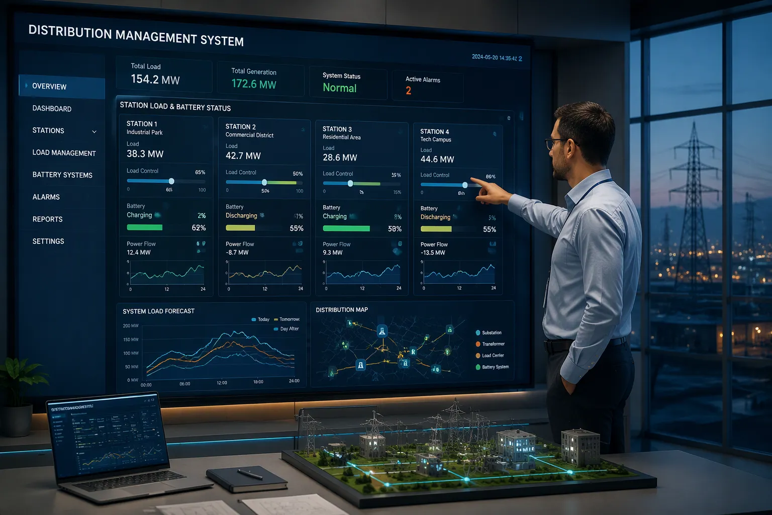
Multi-channel distribution management achieves precise independent control by giving every station load and every battery its own dedicated power conversion and control channel. You can then regulate all of them at once, with no cross-interference. Shared-bus or single-channel designs tie loads together on one conversion path. That approach suits simpler sites well, yet it cannot decouple one battery's charging from another load's discharging.
This matters in integrated power systems, where microgrids, battery energy storage, coordination, energy management, and energy scheduling all depend on clean separation. ESTEL's multi-channel platform and Smart Power Distribution Unit show how the architecture, control mechanism, benefits, and implementation considerations fit together.
Key Takeaways
Multi-channel distribution gives each load and battery its own control channel. This allows precise independent control without interference.
Isolation between channels prevents faults from spreading. It keeps other loads and batteries running safely.
Coordinated control strategies balance independent channels to meet site-wide goals. This improves efficiency and reliability.
Battery degradation-aware optimization extends battery life. It reduces costs by avoiding unnecessary stress.
Proper planning of channel capacity and operating modes ensures microgrids run smoothly. It maximizes value and resilience.
Multi-Channel Architecture in Integrated Power Systems
Dedicated Channels per Load and Battery
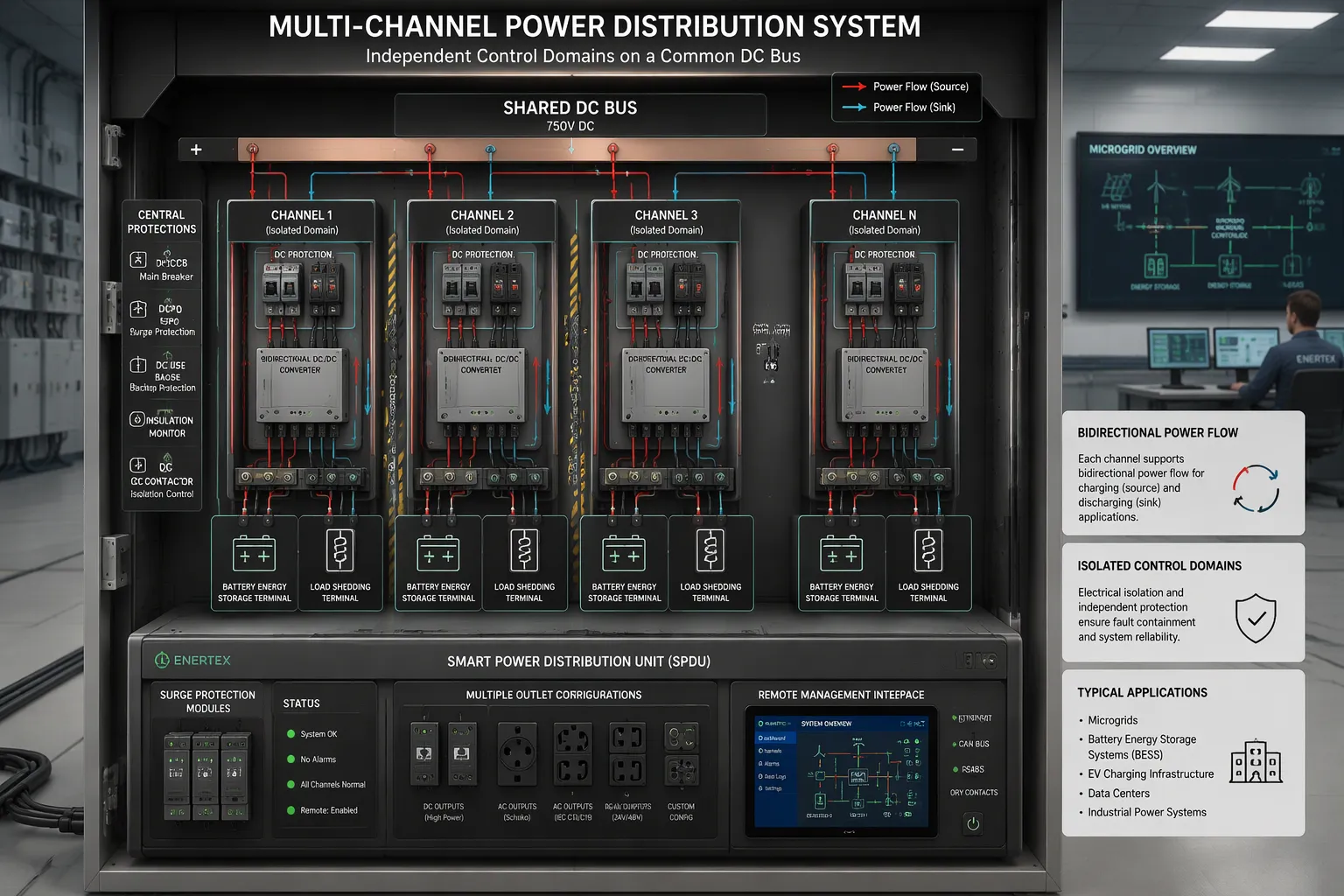
Each substation in integrated power systems can manage a distributed network of energy storage terminals and precise load shedding terminals. Multi-channel distribution management is the hardware layer that makes this possible. Every battery energy storage system terminal and every load gets its own conversion path, so a change on one channel never ripples into another.
A shared DC bus carries power across the site, and isolated conversion domains sit on top of it. ESTEL's Smart Power Distribution Unit fits here as the power distribution and protection layer. It offers multiple outlet configurations, surge protection, and remote management, so you can wire each channel to its own protected feed.
Traditional multi-channel supplies carry real limits, as Action Power Test notes. Most operate only in the first quadrant and cannot sink power, so two-way power flow testing needs an extra electronic load. Most are DC-only, and many independent AC channels are expensive and bulky. Fixed output configurations also lock you into a set number and rating of outputs.
Limited to first quadrant (source only), with no sink capability
DC-only output in most designs
Fixed output configurations rather than configurable slots
Wiring complexity for advanced features such as bidirectional flow
Neither approach wins everywhere. A shared bus suits small sites with uniform loads and tight budgets. Isolated channels fit sites where battery energy storage systems, load power control unit functions, and grid-connected microgrids must run at once.
Isolated Control Domains on a Common Bus
Isolation keeps each control domain independent. BitEchipc's engineering guidance ties the choice to deployment conditions. A short segment inside one cabinet with one supply and a verified common ground usually works without isolation. Nodes in different cabinets or on different supplies need isolation, because ground offset is unknown and shifts with load. Battery racks or battery management systems at different potentials call for isolation, preferably per channel.
Deployment condition | Typical choice | Reason |
|---|---|---|
Short segment, one cabinet, verified common ground | Non-isolated is usually acceptable | Small, controlled ground offset |
Nodes in different cabinets or supplies | Isolated | Ground offset is unknown and load-dependent |
Battery racks or BMS segments at different potentials | Isolated, preferably per channel | Segments may not share a ground plane |
Isolation protects the node that has it. It does not make other nodes immune, and you do not need it on every node by default. A digital isolator only creates a domain when the bus-side transceiver runs from an isolated supply. Check the isolated DC/DC converter's own rating and where the shield terminates. Grid Connect notes that a 3kV isolator includes a 120 Ohm termination resistor on the primary side only, so your two-resistor bus strategy still applies.
Achieving Independent Control and Coordinated Control Strategies
Decoupled Power Flow and Control Loops
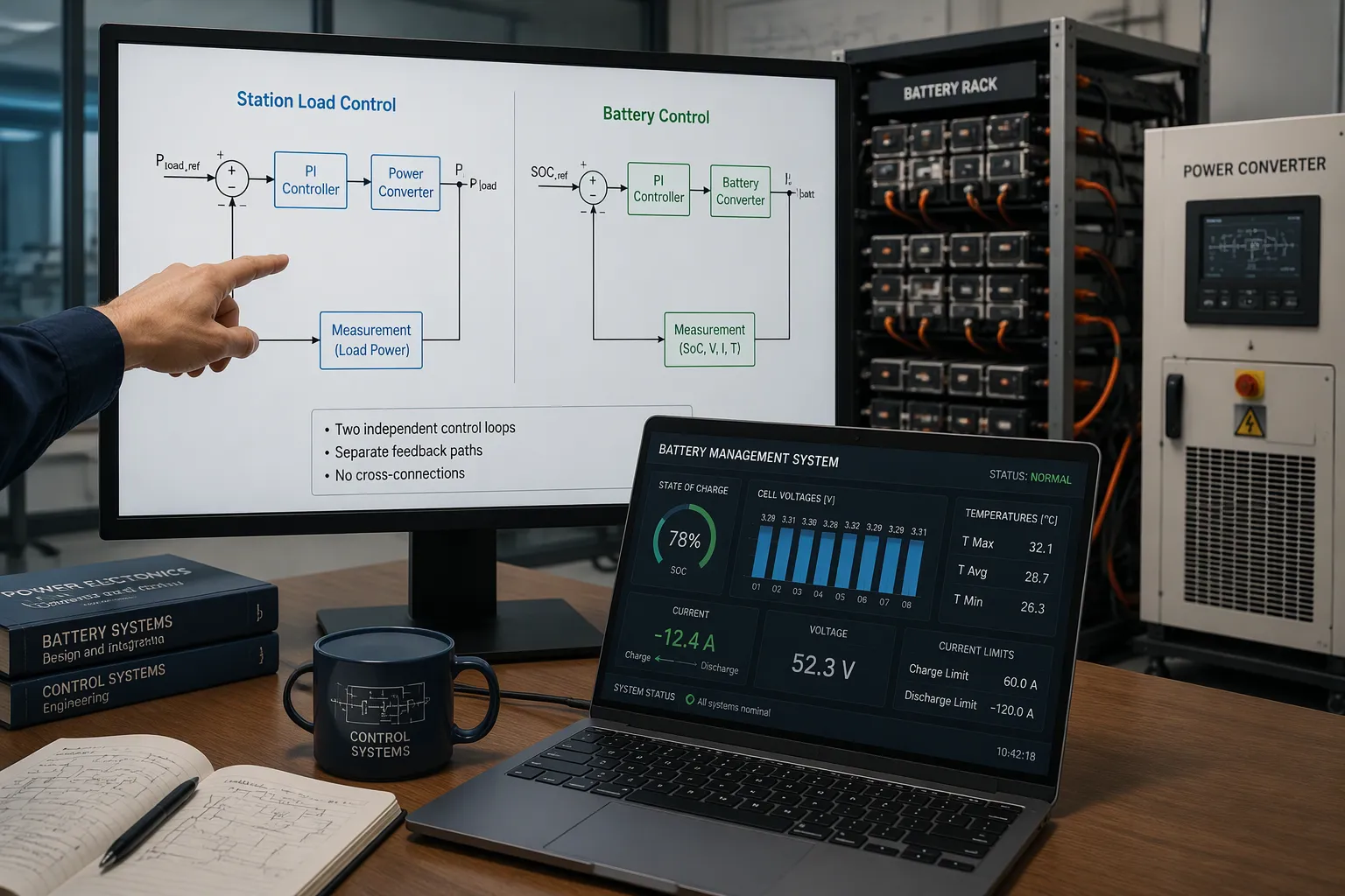
Each channel runs its own control loop. One loop regulates a station load. Another loop regulates a battery. Neither loop sees the other's error signal. This separation lets you run all channels at once without cross-interference.
Research published in PMC describes a diagonal matrix decoupling network that eliminates power coupling between ports. The same study reports dynamic response times of about 20 to 35 ms after sudden load changes on one port, with voltage fluctuations on the other port staying near 0.2 to 0.6 V. That result shows real decoupling: a disturbance on one channel barely moves its neighbors.
Stability still needs attention. The Encyclopedia of Power Conversion notes that weak grids raise power angle dynamics, which affect controller gain and bandwidth. You may need a lower controller bandwidth to keep a stability margin. Design your loops for the weakest grid condition you expect, not the strongest.
Real-Time Regulation of Loads and Batteries
Battery management systems supply the data that makes precise charging and discharging possible. Per Sunlithenergy, the BMS sends real-time charge and discharge limits—maximum current, minimum cell voltage, and thermal boundaries—that the converter must always respect. The BMS also transmits state of charge, state of health, cell voltages, temperatures, and fault codes.
State-of-charge estimation carries error under stress. PatSnap reports that SOC miscalculations can exceed 8 to 12 percent in extreme cases when cells run above 45°C during fast discharge. Active cooling that holds cell temperature within 5°C variance cuts SOC estimation errors by roughly 40 percent compared with passive cooling. Treat SOC as an estimate, and let current limits do the hard protection work.
Timing matters too. Sunlithenergy states that the energy management system link to the power converter must have round-trip latency below 50 ms. Wattmore notes that the EMS sends active power setpoints at 1-second intervals. Your control architecture must respect both timescales.
Coordinated control strategies sit on top of independent channel control. Consider peak shaving across several battery energy storage stations. Each station's battery energy storage system keeps its own limits. A higher layer allocates power setpoints across stations to hit a site-level target. This is coordination without coupling: the stations share a goal, not a control loop.
Benefits: Reliability and Battery Degradation-Aware Optimization
Fault Isolation and Load Prioritization
A fault on one channel stays on that channel. You keep the other station loads running, and you keep every other battery charging or discharging on its own schedule. Precise load shedding terminals then protect priority loads by selectively supplying power to loads that matter most. This isolation is what makes integrated power systems dependable under failure, not just under normal operation.
The same logic supports resilience planning in microgrids. RMI finds that non-residential backup options generate significant net value over a 20-year timespan, and a subscription service plus diesel generator returns roughly $1.7 million, about $200,000 more than customer-owned backup power. You gain those returns only when a single failure cannot take down the whole site.
Efficiency, Battery Life, and Cost
Battery degradation-aware optimization turns charge and discharge limits into money. Oak Ridge National Laboratory reports a Bayesian optimization framework that converges to the optimum within 20 iterations out of 150 possible sizes, and it consistently picks the smallest feasible system to avoid degradation costs from oversized storage. PatSnap notes that adaptive charging strategies and thermal management cut stress, while LG Energy Solution's predictive analytics extend battery life by up to 20 percent. Mobility House adds that intelligent operation can extend the lifecycle by one to two years in many cases.
Smaller, right-sized storage avoids unnecessary degradation cost
Adaptive charging and thermal control reduce cell stress
Longer asset life raises total lifecycle revenue and lowers warranty risk
Cost savings follow from better utilization. Arevon Energy reports that Texas storage deployments saved consumers $750 million in summer 2024 alone. Your energy management, energy scheduling, and coordination layers decide how much of that value you capture, and distribution design sets the ceiling.
Implementation in Microgrids and Station Design
Sizing Channels and Operating Modes
Start with a load analysis. Map peak and average demand, separate critical from non-critical loads, and project future growth. Chint Global notes that this analysis feeds generation and storage sizing, then distribution architecture, protection settings, and control logic. Size storage around critical load duration, not only daily shifting. Sizing around average demand misses cloudy weeks and long outages.
Storage sizing depends on critical load, outage duration, renewable output, tariff strategy, and seasonal patterns.
Off-grid microgrids need more generation reserve, more storage, and tighter load controls.
Hybrid microgrids switch modes but raise protection and control demands.
Check protection settings in both grid-connected and islanded modes, because fault current changes.
Microgrids with variable solar and wind inputs benefit from flexible channel allocation. You can reassign a channel as the resource mix shifts. Plan operating modes before you order equipment. Specify transition logic, load priority, and restart sequence for grid-connected microgrids that move to islanded operation.
Monitoring and ESTEL Platform Integration
Real-time monitoring and control unites data across the system. Fortinet explains that continuous visibility into performance metrics and device health lets teams detect faults early and cut downtime. Hitachi Energy's distribution management platform adds outage prediction, fault location, and restoration tools for operational decisions during outages. Splunk notes that centralized views let engineers track device health without checking each unit manually.
Your microgrid energy management systems and microgrid energy scheduling layers depend on this data. Integrated energy management systems turn raw telemetry into setpoints, and optimized BES dispatch follows. Battery management systems feed state of charge and current limits into the same stream, so charging stays within safe bounds.
ESTEL's Smart Power Distribution Unit supports integration through several features.
Feature | Benefit |
|---|---|
Remote power management | Control from anywhere; faster troubleshooting |
LCD monitoring | Real-time visibility at the rack |
Dehumidifying function | Maintains optimal operating conditions |
IEC60309-compliant plug system | Standardized, safe connections |
Separate channels create decoupled control. Decoupled control lets you regulate station loads and battery charging or discharging at once, with precision. That chain lifts reliability in integrated power systems, improves battery utilization through battery degradation-aware optimization, and cuts operating cost.
Microgrids, grid-connected microgrids, battery energy storage, and distribution design all rest on this. Energy management, energy scheduling, coordination, and control turn channels into results. Energy management and energy scheduling guide battery energy storage. Coordination and control link microgrids and battery energy storage. Energy management, energy scheduling, coordination, control, and distribution shape every microgrids project.
ESTEL's multi-channel distribution management and Smart Power Distribution Unit support scalable, flexible stations. Evaluate your channel architecture and loads.
FAQ
How do separate channels keep station loads and batteries independent?
Each channel runs its own control loop, so one battery never disturbs another. In microgrids, this separation lets energy management reach every unit at once. Microgrids with mixed demand gain the most. Energy management stays clean because microgrids keep domains isolated, and energy management never fights itself. Distribution wiring follows the same split, and station loads stay separate.
How does a battery management system support precise charging?
The battery management system reports state of charge and current limits. Your control layer respects those limits on every cycle. Coordination between the battery and converter keeps charging safe. In microgrids, energy management uses this data. Microgrids trust energy management for safe cycling. Microgrids gain when energy management and coordination share one stream.
Why does coordination matter across multiple battery stations?
Coordination allocates power setpoints across stations toward one site goal. Energy management owns that layer. Microgrids need it for peak shaving. Energy scheduling sets the timing, and microgrids depend on energy scheduling for daily cycles. Microgrids without coordination drift. Energy management without coordination drifts too. Microgrids pair energy management with coordination for stable output.
What role do microgrid energy management systems play?
Microgrid energy management systems turn telemetry into setpoints. Microgrid energy scheduling plans the daily charge window. Energy management and energy scheduling must agree. Microgrid energy management systems feed dispatch in microgrids, and microgrids' control follows. Energy scheduling guides microgrids' storage. Energy management guides microgrids' targets.
How do you plan channel capacity for microgrids?
Map peak demand and outage duration first. Size storage around critical duration, not average demand. Energy scheduling sets charge windows. Energy scheduling sets restart order. Microgrids with solar and wind need flexible channels. Energy management and energy scheduling plan modes. Coordination and distribution design set the ceiling. Microgrids reward early planning. Energy management ties it together.
See Also
Grid-Tied Solar Inverter and Battery Setup for Telecom Cabinets
Calculation Methods for Telecom Cabinet Power Systems and Batteries
Solar Energy Storage Power System for Telecom Cabinet Applications
ESTEL Smart Microgrid Integrated Energy Storage for Telecom Cabinets
Ensuring Reliable Power Supply for Telecom Cabinet Operations
CALL US DIRECTLY
86-13752765943
3A-8, SHUIWAN 1979 SQUARE (PHASE II), NO.111, TAIZI ROAD,SHUIWAN COMMUNITY, ZHAOSHANG STREET, NANSHAN DISTRICT, SHENZHEN, GUANGDONG, CHINA
