Smart Dynamic Current-Limiting Technology for Integrated Power Systems: Shielding Upstream Diesel Generators and Weak Grid Infrastructure

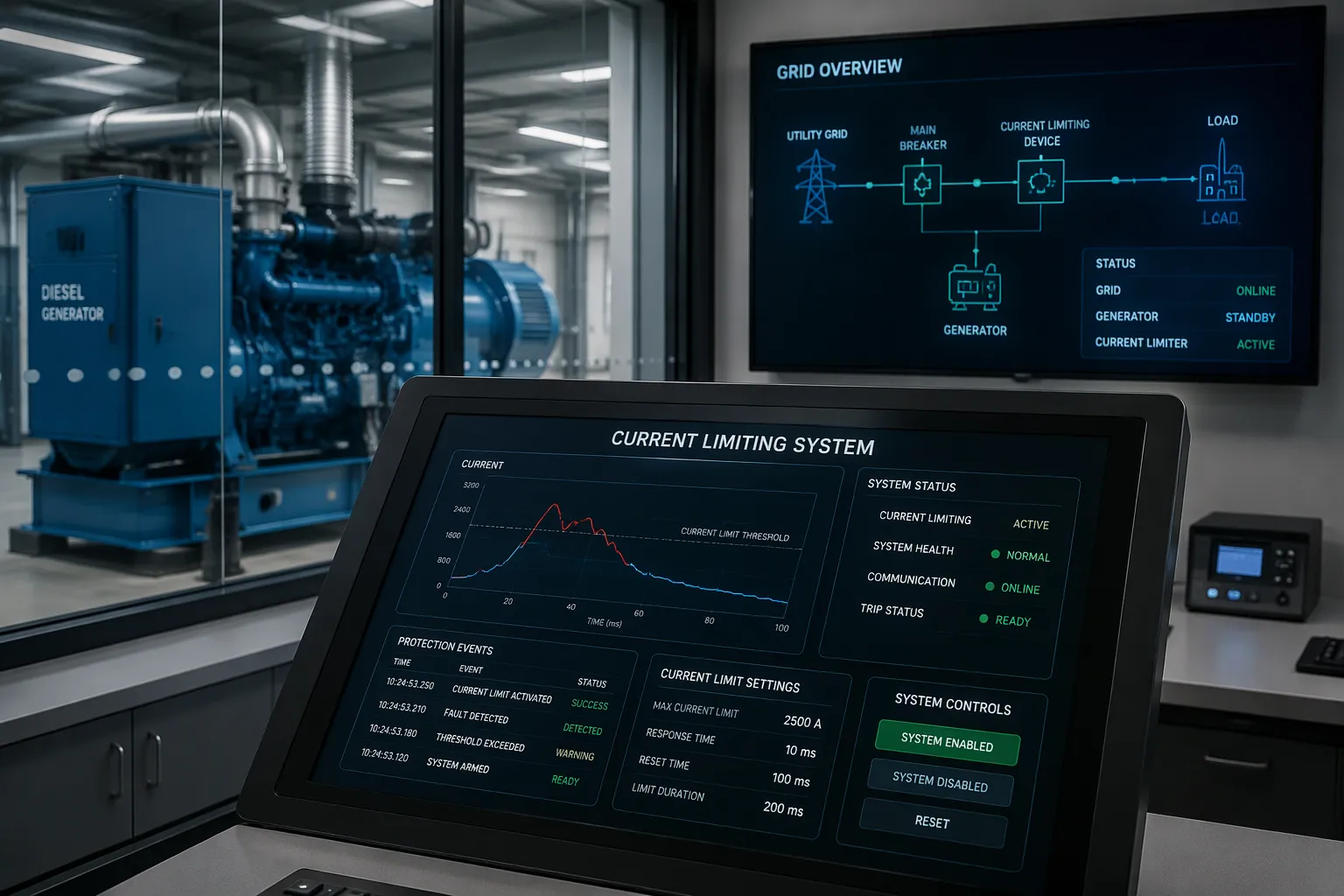
Smart dynamic current-limiting technology is an active, fast-response device. It inserts controlled impedance to cap fault current within milliseconds. This capability matters in integrated power systems. Diesel generators and weak grids have limited fault withstand and low short-circuit capacity. Conventional protection often reacts too slowly or too coarsely for them. A fault current is the surge of current a short circuit drives through the network. Short-circuit capacity describes how much current a source can deliver during that event. You will see the fault and stability problem, learn how the technology works, and review its shielding benefits. The article then compares the technology with alternative protection methods and identifies where it fits best.
Key Takeaways
Smart dynamic current limiters cap fault current within milliseconds to protect equipment.
They shield diesel generators from thermal and mechanical stress during faults.
They stabilize weak grids by reducing voltage and frequency dips.
Dynamic limiting complements fuses, reactors, and breakers; it does not replace them.
Best fit: low-short-circuit, generator-backed systems like microgrids and remote sites.
Fault Current Challenges in Integrated Power Systems
Diesel Generator Vulnerability
Upstream diesel generators face a hard limit on fault withstand. Their windings and connected equipment endure severe thermal and mechanical stress when a fault drives high current through them. Industrial Monitor Direct notes that solidly grounded neutral systems are not used at medium voltage levels because earth faults produce unacceptably high energy release during short circuits.
Solidly grounded systems should be avoided on MV generators due to unacceptable energy release during earth faults.
You can quantify the thermal side with a simple relation. Power dissipation follows P = I² × R, and energy equals P × t. A generator with modest resistance still absorbs enormous energy when fault current is large and clearing is slow. LinkedIn's earth-fault protection guidance for diesel generator sets offers these selection points:
Select the neutral grounding resistor time rating (for example 10 s, 30 s, or 1 min) based on relay operating time and backup protection clearing time.
Incorrect selection can cause excessive equipment damage.
Weak Grids and Low Short-Circuit Capacity
Weak grid infrastructure has low short-circuit capacity and high impedance. Voltage and frequency dips become pronounced during faults and load steps. Watt-Logic describes how inverters must stay connected during low-voltage faults and switch from power-maximising to voltage-support mode. The inner control loop then operates in two regimes, and transitions between them produce current spikes as large as a full ac cycle's peak current.
Fault current from inverters is smaller, highly distorted, and rich in harmonics. Watt-Logic reports that at fault onset the dc component can reach around 34% of the fundamental amplitude, while the second harmonic can reach roughly 39%. Conventional over-current and distance relays assume a simple 50 Hz sinusoid plus a dc offset, so they may miscalculate impedance or direction. In weak grids, frequency and voltage couple, and lower inertia speeds up electromagnetic state changes. High DER penetration, FACTS devices, and dynamically changing grid conditions create protection challenges. These conditions demand field-deployable solutions for integrated power systems.
How Smart Dynamic Current Limiting Works
Core Components and Sensing
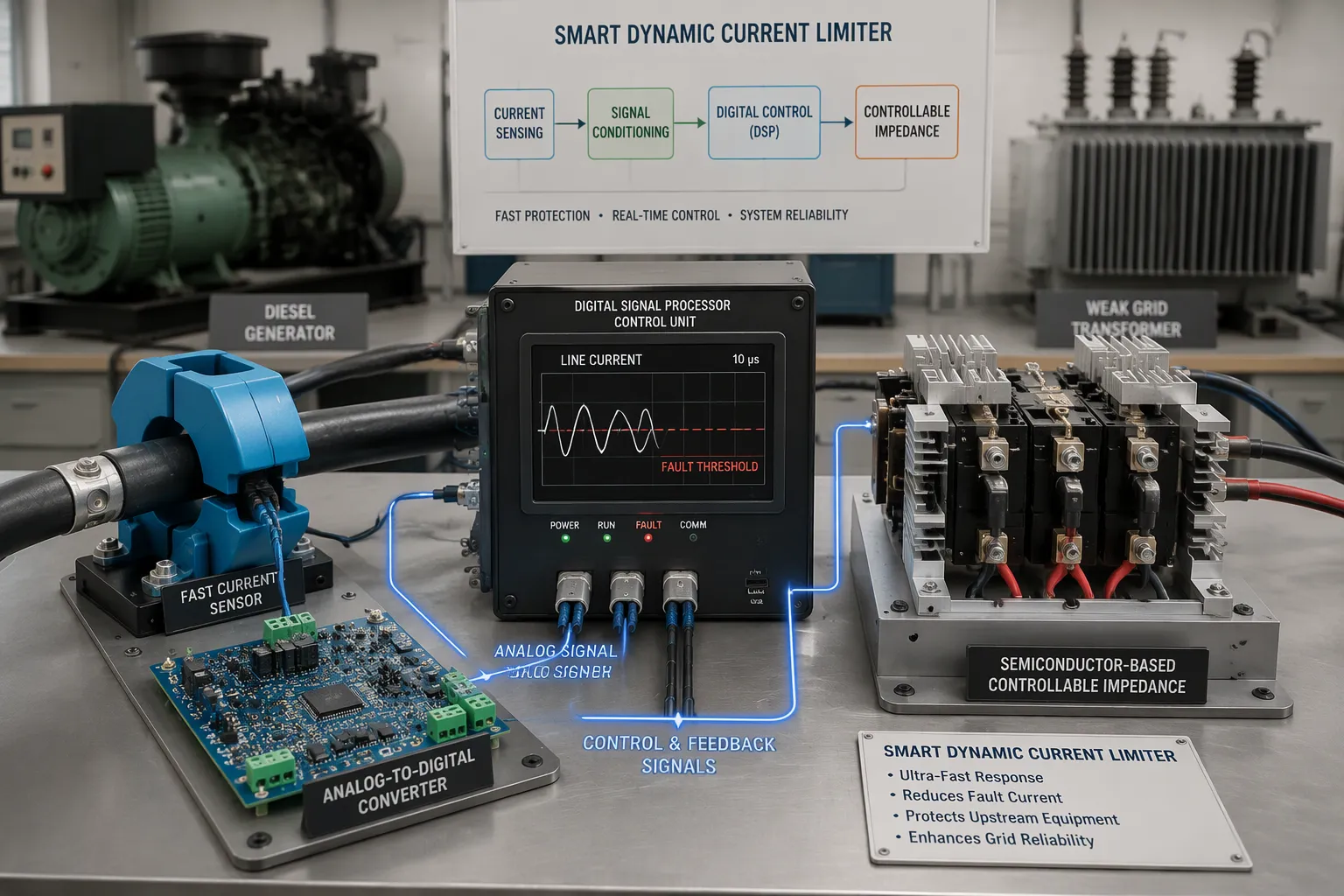
A smart dynamic current limiter relies on three building blocks. Fast sensing captures the instantaneous current waveform. A controllable impedance element sits in the current path. A control unit ties the two together and decides when to act. Impedance is the opposition a circuit presents to alternating current, and it combines resistance with reactance.
Detection can run at the hardware level through analog comparators or at the software level through current sensing. An arxiv paper on solid-state transformer protection describes a typical software condition: a fault is flagged when the DC current exceeds a fault threshold and its rate of change exceeds a separate threshold at the same time. Because the current is already sensed in the original control loop, this comparison needs no extra hardware. The same paper gives a concrete timing budget. Analog-to-digital conversion plus sensor response takes 5 µs, and optical fiber transmission takes another 5 µs. The digital signal processor therefore receives instantaneous current information within 10 µs, which the authors call acceptable for solid-state transformers operating at low frequencies such as 100 kHz.
Dynamic Response and Control Logic
Response speed separates this class of device from passive parts. PatSnap reports that semiconductor-based current limiters switch within microseconds to current variations. The same source notes that ABB's superconducting fault current limiter transitions from superconducting to resistive state within milliseconds. A PTC thermistor, by contrast, responds at the millisecond level and suits only slower inrush events.
The control logic follows a staged sequence. When the fault is flagged, the processor first disables the switches to keep current from climbing too high. It then waits until the current discharges to a system-friendly level. At that point the current-limiting controller takes authority. The arxiv paper describes a two-part strategy: the controller holds a designated current level under low impedance long enough for fuses or breakers to isolate the faulted branch, then a rate-limited recovery stage restores nominal operation without excessive inrush during recharge.
Grid-forming converters offer a useful reference model. A grid-forming converter is an inverter that sets its own voltage and frequency reference rather than following the grid. Keentel Engineering explains that virtual impedance current limiting subtracts a synthetic voltage drop from that reference, and the impedance magnitude must be at least the reference voltage divided by the maximum current. This approach keeps voltage-source behavior but acts more slowly and reduces small-signal margin. The same source notes that a purely resistive virtual impedance can destabilize a unit through a small critical clearing angle, while an inductive one raises that angle, and a reactance-to-resistance ratio near 5 has been proposed as a workable compromise. A Nature study of hybrid grid-forming inverters found their active power output briefly exceeded 1.1 per unit for less than 30 ms after a load step, within the short-term rating allowance of IEEE Std. 2800-2022, and system settling time was approximately 15 s.
Shielding Generators and Weak Grids
Protecting Upstream Diesel Generators
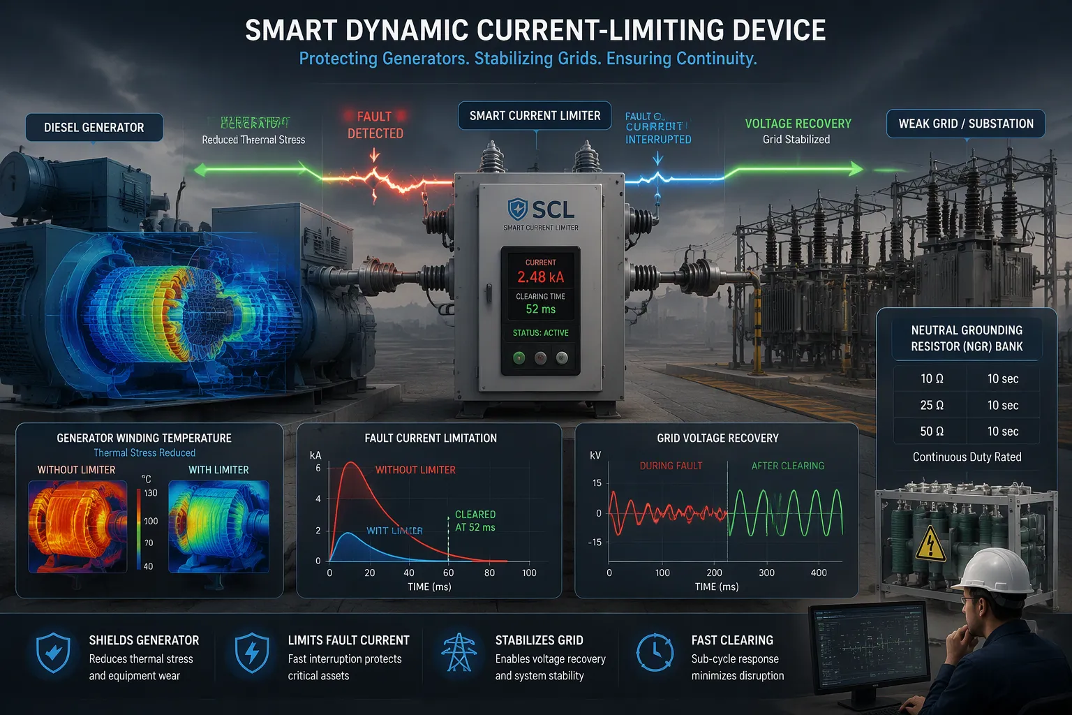
A diesel generator has a fixed thermal budget. Fault current spends that budget quickly. The energy absorbed by the windings follows power equals current squared times resistance, and total energy equals that power multiplied by clearing time. Double the current and you quadruple the heating rate. A smart dynamic current limiter cuts the current magnitude at the source of the fault, so the generator never sees the full contribution. The winding temperature rise falls sharply, and the mechanical forces on the end windings and shaft drop with it.
You also gain time. The limiter holds a controlled current level long enough for downstream fuses or breakers to isolate the faulted branch. The generator keeps running through the event instead of tripping. Recovery then proceeds faster, because the machine has not lost excitation or suffered insulation damage. Neutral grounding resistor selection still matters here. Choose the resistor time rating, such as 10 s, 30 s, or 1 min, against relay operating time and backup clearing time. A limiter reduces the current the resistor must absorb, and that margin protects the equipment from excessive damage.
Stabilizing Weak Grid Infrastructure
Weak grids struggle with two problems at once. Short-circuit capacity is low, and impedance is high. A fault pulls voltage down deeply, and frequency follows. Inverter-based sources make the picture harder. Their fault current is small, distorted, and rich in harmonics. At fault onset the dc component can reach around 34% of the fundamental amplitude, and the second harmonic can reach roughly 39%. Relays that assume a clean 50 Hz sinusoid may misjudge impedance or direction.
A dynamic limiter supports the grid in several ways. It caps the fault current that propagates toward upstream equipment, so the disturbance stays local. Voltage recovery starts sooner, because the limiter releases its impedance once the fault clears. Frequency stays closer to nominal, since the source does not lose a large block of generation. Grid-forming references show what good behavior looks like. A hybrid grid-forming inverter briefly exceeded 1.1 per unit of active power for less than 30 ms after a load step, within the short-term rating allowance of IEEE Std. 2800-2022, and system settling time was approximately 15 s. A limiter that mimics this controlled response helps a dynamic microgrid ride through faults and load steps without cascading trips.
These benefits compound in integrated power systems that mix diesel generation, batteries, and photovoltaic sources. Each source has its own fault signature. A fast, controllable impedance gives you one coordination layer that works across all of them. The result is a network that absorbs disturbances instead of amplifying them.
Comparison With Alternative Protection Methods
Performance and Application Fit
Each option solves a different slice of the fault problem. Fuses clear a fault by melting, and they cost little, yet you must replace them after every operation. Current-limiting reactors add fixed impedance in series. They respond instantly and need no sensing, but they drop voltage during normal load and cannot adapt to changing conditions. Mechanical breakers interrupt current reliably and handle high fault levels, though their operating time is slow relative to a fast fault rise.
Solid-state fault current limiters (SSFCLs) switch within microseconds to current variations, and superconducting designs transition to a resistive state within milliseconds. A PTC thermistor responds at the millisecond level and suits only slower inrush events. FACTS devices offer continuous control of voltage and power flow, and they can defer infrastructure investment by raising the capacity of existing lines. The table below places each option where it fits best.
Option | Strength | Best fit |
|---|---|---|
Fuse | Low cost, simple | Branch isolation on small feeders |
Current-limiting reactor | Instant, passive | Fixed impedance on stable networks |
Mechanical breaker | High fault interruption | Primary switching and isolation |
SSFCL | Microsecond response | Fast, repeatable current capping |
FACTS device | Continuous control | Voltage support and capacity deferral |
Compliance and Cost
Regulatory compliance shapes the choice as much as performance does. Breakers and fuses carry well-established standards and test regimes, so approval is straightforward. SSFCLs and dynamic limiters face newer standards, and you should confirm the applicable test limits before you specify one. Cost follows the same pattern. Fuses and reactors carry low capital cost. Breakers sit in the middle. SSFCLs and FACTS devices cost more up front, yet FACTS devices can defer capital spending on new lines and substations, which improves their cost-effectiveness over a project's life.
ESTEL supplies integrated power distribution and protection solutions for these integrated power systems, and the company offers several of these options. Match the device to the fault level, the generator withstand rating, and the regulatory regime at your site. No single method wins everywhere.
Application Guidance With ESTEL Solutions
Typical Deployment Scenarios
You will find dynamic current limiting most valuable in four settings. Generator-backed sites come first, because a diesel set has a fixed thermal budget and little tolerance for sustained fault current. Remote telecom sites follow, where a single weak feeder supplies the load and a fault can isolate an entire cell site. Microgrids with battery energy storage and photovoltaic arrays form the third case, since each source adds its own fault signature. Weak-grid interconnections complete the list, where low short-circuit capacity makes voltage and frequency dips severe.
KDS Electrical notes that modern power system cabinets can act as a microgrid hub, managing inputs from solar arrays and battery systems while coordinating with the grid. That hub role suits these scenarios well. A cabinet-level layout also lets you add or remove components without major cable rewiring, which keeps maintenance and upgrades practical.
Smart Power Distribution Unit Integration
ESTEL's Smart Power Distribution Unit serves as the distribution and protection coordination layer inside an ESTEL outdoor telecom cabinet or power system. It brings surge protection, remote management, and a choice of 8 to 19 outlets. Configurations include a 16A maximum input current and 230VAC 32A rated models, with a cable plug system compliant with IEC60309. Alibaba's buying guide notes that a designated cabinet PDU arrives pre-validated for its cabinet class, which reduces engineering overhead and audit risk.
Selection and sizing follow a clear sequence. Compare peak, symmetrical, and sustained fault levels against breaker ratings, then check I²T let-through and withstand duration, as Industrial Monitor Direct advises. Request a transient stability study with actual generator parameters to confirm the critical clearing time. If that time falls below your trip setting for any operating point, reduce the trip regardless of breaker rating. Finally, weigh dynamic current-limiting options against regulatory and cost criteria for your integrated power systems.
Smart dynamic current limiting caps fault current within milliseconds. That speed shields diesel generators from thermal and mechanical stress. It also steadies weak grids during voltage and frequency dips. Passive reactors and mechanical breakers cannot match this response time.
Treat the technology as a complement, not a replacement. Fuses, reactors, and breakers still handle isolation and switching. Dynamic limiting works best in low-short-circuit, generator-backed systems.
Start with an assessment. Measure your fault levels and generator withstand ratings. Then weigh dynamic current-limiting options, including ESTEL integrated power solutions, against your regulatory and cost criteria.
FAQ
What does a smart dynamic current limiter actually do during a fault?
It senses the fault current and inserts controlled impedance within milliseconds. That action caps the current before it reaches upstream equipment. Once the fault clears, the device restores normal operation through a rate-limited recovery stage. You get fast current capping without permanent series impedance during healthy operation.
Why can't a standard breaker protect my diesel generator on its own?
A breaker interrupts current, but it acts slowly relative to a fast fault rise. Generator windings absorb energy at a rate that rises with the square of current. Slow clearing lets that energy accumulate. A limiter reduces the current magnitude first, so the generator sees far less thermal and mechanical stress.
How does dynamic limiting differ from a current-limiting reactor?
A reactor adds fixed impedance at all times. It responds instantly and needs no sensing, but it drops voltage during normal load and cannot adapt. A dynamic limiter inserts impedance only during a fault. That difference matters on weak grids, where you want full voltage during healthy operation.
Where does this technology fit best?
It suits low-short-circuit, generator-backed systems. Examples include remote telecom sites, microgrids mixing batteries and photovoltaic arrays, and weak-grid interconnections. In these settings, conventional protection reacts too slowly or too coarsely. Dynamic limiting complements fuses, reactors, and breakers rather than replacing them.
How do I size a limiter for my site?
Compare peak, symmetrical, and sustained fault levels against your breaker ratings. Check the I²T let-through and withstand duration. Confirm the generator's critical clearing time with a transient stability study using actual machine parameters. Then weigh the options against your regulatory and cost criteria.
See Also
Estel Smart Microgrid Integrated Energy Storage System For Telecom Cabinets
Grid Connected Photovoltaic Inverter And Battery System For Telecom Cabinets
Photovoltaic Energy Storage Power System Designed For Telecom Cabinet Applications
How To Ensure Reliable Power Supply For Telecom Cabinet Operations
CALL US DIRECTLY
86-13752765943
3A-8, SHUIWAN 1979 SQUARE (PHASE II), NO.111, TAIZI ROAD,SHUIWAN COMMUNITY, ZHAOSHANG STREET, NANSHAN DISTRICT, SHENZHEN, GUANGDONG, CHINA
