Intelligent Silent Fan Speed Regulation of Telecom Power Systems: Dynamic Noise Reduction Based on Load During Operation

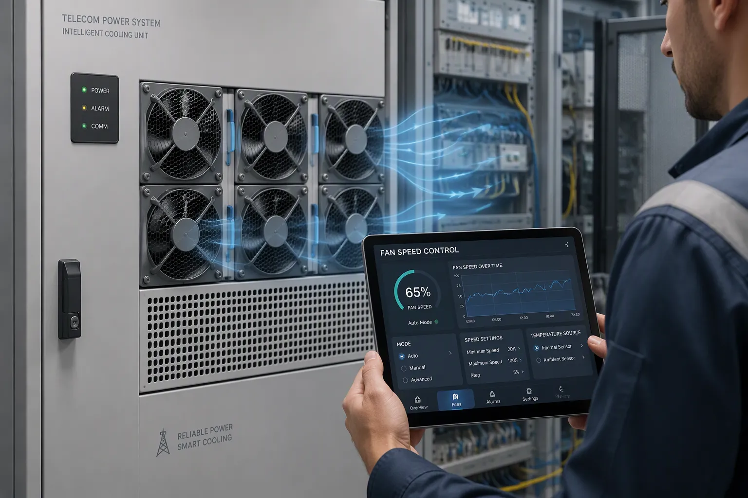
Intelligent fan speed regulation cuts noise by continuously matching fan RPM to the real electrical load of telecom power systems. You get quiet operation at light load, and the fans ramp up only when thermal demand requires it. This matters because fans often dominate the sound profile of telecom cabinets and outdoor sites. Fixed-speed cooling wastes energy and creates needless acoustic disturbance. Smart control changes that. You will see how the control logic works, how load maps to speed, and why the result is low noise without sacrificing thermal safety. The same approach helps you reduce noise across telecommunications sites of every size.
Key Takeaways
Smart fan control adjusts fan speed to the actual electrical load, cutting noise when load is low.
The system uses sensors to measure current and temperature, then sets the fan speed for optimal cooling and quiet operation.
Lower fan speeds save energy, extend fan life, and reduce noise, making the site more comfortable.
You need PWM-capable fans and a controller with a tuned speed curve to implement this system.
Temperature safeguards always override noise targets, so equipment stays safe even in quiet mode.
Load-Based Fan Control in Telecom Power Systems
Sensing Real-Time Load
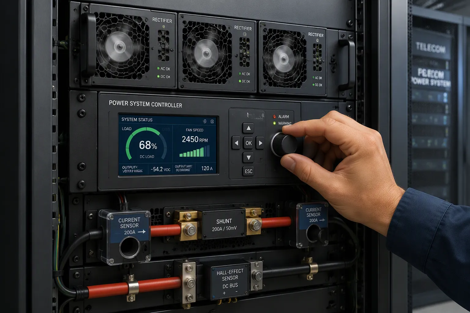
You cannot regulate fan RPM well without knowing the actual electrical load. Three parameters give you that picture: output current, rectifier module load percentage, and DC bus power. Current sensors and shunts measure output current directly. Hall-effect sensors or shunt resistors handle the measurement. The system controller samples rectifier module data to calculate load percentage. Voltage and current sensing together derive DC bus power. These signals feed the controller continuously, so it always knows how hard the telecom power systems are working.
PWM speed control and FG signal output make real-time adjustment possible. The controller sends a pulse-width modulated drive signal to each fan. A higher duty cycle means faster rotation. The fan returns an FG (frequency generator) signal, typically two or three pulses per revolution. The controller reads this feedback and confirms actual RPM against the commanded value. This closed loop enables predictive control: the system anticipates cooling demand changes according to load and adjusts before heat builds up. Predictive cooling control also smooths the response to sudden load steps, which keeps thermal performance stable.
ESTEL's Telecom Power System illustrates one fitting option. It accepts a wide 90–300 Vac AC input, uses natural cooling, and installs on a standard 19-inch rack or inside a cabinet. The 2U chassis fits standard telecom racks. Multiple communication ports support integration with the fan control loop. This design suits many deployments, and where fans are added for higher heat loads, the communication ports let the controller coordinate them. This arrangement keeps cooling performance predictable across telecommunications equipment and supports quiet telecom power systems.
Mapping Load to Fan Speed
Simple load thresholds are the entry-level approach. The controller defines two or three load bands, and each band sets a fixed fan RPM. This works well for sites with stable, predictable load profiles. The logic is easy to commission and easy to troubleshoot. Predictive control can refine this simple scheme.
Proportional or continuous mapping fits sites with widely varying load. The controller computes a target RPM from the load signal along a defined curve. Light load produces a low average fan speed. As load rises, RPM climbs smoothly. This approach avoids the abrupt acoustic steps of threshold control and tracks demand more precisely. Predictive control adds a further layer: the algorithm watches load trends and ramps RPM ahead of the thermal rise, which protects thermal stability during sudden traffic bursts. Predictive cooling control of this kind also reduces noise at night, when traffic drops and demand falls. You can tune the curve during commissioning to match the site's measured load profile.
Both methods rely on PWM speed control for fine resolution. The controller can hold an optimized speed that matches demand exactly, rather than jumping between fixed settings. Predictive control can layer on top of either method. For sites in noise-sensitive locations, continuous mapping usually delivers the quieter result. For small remote sites with steady loads, thresholds remain a practical, low-cost choice. The controller also monitors temperature as a safeguard, so RPM rises if heat exceeds the expected level for the current load. Either way, the fans run only as fast as the load requires, and that is the heart of quiet operation in telecommunications.
The Dynamic Noise Reduction Mechanism
Fan Speed and Noise
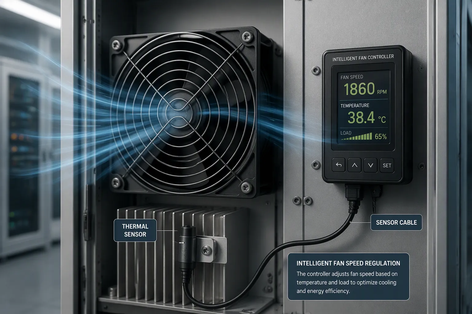
Cooling fan noise is a system property. Thermal design, mechanical design, and fan selection shape it as much as the fan's own acoustical design. Aerodynamic sound appears when air flows across rotating fan blades and interacts with surrounding surfaces. High fan speed is one primary cause. Turbulent airflow, poor airflow path design, and obstructions near the fan inlet or outlet add to it. In high-airflow industrial cooling systems, this is typically the dominant source. Fan placement and grille losses change the sound you hear at the cabinet.
You can address this at the source. Aerodynamic improvements can cut hum or drone while improving efficiency. Good noise control begins with fan selection. Variable-speed control lets fan RPM track thermal load. When the fan lowers its RPM under reduced load, it avoids wasting energy on excess airflow, and the acoustic output drops accordingly. This RPM-to-noise relationship explains why EC fans outperform fixed-speed fans on noise-to-performance balance. Higher fan speed corresponds to higher sound levels. Select a fan and controller pair that supports closed-loop or PWM control, so the fans follow temperature rather than running at a fixed ceiling. Confirm the control method (PWM, CAN, LIN, or analog) fits the system electronics.
Intelligent Control Logic
The controller balances thermal headroom against acoustic output. It reads load and temperature, then sets a target RPM that keeps heat in check without overshooting. Hysteresis prevents oscillation. The controller ignores small temperature swings around a setpoint, so the fans do not hunt up and down. Temperature safeguards override the acoustic logic. If heat exceeds the expected level for the current load, RPM rises regardless of the noise target. Suppressing acoustic whine in PWM speed control is a practical technique. The drive frequency sits above the audible band, or the controller shapes the waveform to avoid tonal whine. The controller also checks that commanded RPM matches the FG feedback, so a stalled fan triggers an alarm.
A predictive cooling system adds foresight. Predictive control reads the demand slope, not just the current value. Predictive control of this kind protects thermal performance during traffic bursts. Model predictive control extends this by projecting several steps ahead. Predictive control also cuts sound at night, when demand falls. Predictive cooling control keeps the average fan speed low across the day. Predictive cooling control pairs the demand signal with a thermal model. Predictive control supports lower noise without extra hardware. Predictive control smooths the response to sudden demand steps. Cooling performance stays stable at a telecom site with varying traffic.
You set acoustic targets alongside the thermal limit during design review. Link them to fan speed, placement, and grille losses. Verify acoustic performance at the lowest, nominal, and highest expected RPM points. Confirm the sound target reflects the actual operating profile, because a fan that is quiet at 30% load can become unacceptable at full ramp-up. Document the RPM curve and the temperature override points for the commissioning team, and revisit them after the first seasonal demand cycle. This approach suits telecommunications equipment in noise-sensitive locations.
Benefits of Silent Load-Based Regulation
Energy and Fan Life
Load-based regulation pays you back twice: once on the power bill and once on fan longevity. Modern DC fans for telecom shelters use advanced electronic commutation to minimize energy waste. The controller adjusts fan speed to the real-time thermal load, so the system saves significant power during cooler periods. This intelligent ventilation approach lowers operational cost and extends the life of the DC centrifugal fan. The lifespan gain comes from reduced unnecessary wear on bearings and motor components.
The mechanism is straightforward. Intelligent fan control using PWM or thermostatic sensors varies fan speed according to real-time temperature feedback. The fan no longer runs at constant full speed when cooling demand is low. The system holds proper thermal control while drawing minimal power. This reduced, demand-based operation earns credit for extending fan life. You replace fewer fans, and you schedule less maintenance.
Acoustic Comfort and Reliability
Quieter cooling changes how people experience a site. Lowering average fan speed reduces noise, and customers perceive the difference immediately. Satisfaction rises and complaints fall. Predictive control pre-cools before known load spikes and avoids running fans at full speed during short bursts. That behavior preserves acoustic targets in shared office environments.
Telecom rooms do not forgive acoustic drift, underscoring that noise-to-performance balance in cooling fans is a design priority for telecom deployments.
Benefit Dimension
What It Delivers
General acoustic effect
Lower average fan speed cuts noise; customers notice at once
Telecom-specific benefit
Predictive control pre-cools ahead of load spikes and avoids full-speed bursts, holding acoustic targets in shared spaces
Pilot result
A telecom OEM pilot cut average fan speed by 20% across typical office-day profiles and trimmed peak excursions by 3–5 °C
That pilot shows the practical payoff. You gain low noise without giving up cooling performance. Steady, moderate fan speed also means stable acoustic performance across the day, which supports low-noise operation in noise-sensitive telecommunications sites. Predictive control keeps the loop calm, so you get lower noise and dependable thermal safety together.
Implementing Silent Regulation in Telecom Power Systems
Design, Sensors, and Algorithms
Start with fan selection. Choose PWM-capable fans with tachometer feedback, because the tach wire reports actual blade speed and confirms the commanded duty. A pulse sensor outputs a high/low waveform, and a locked rotor shows a constant high or constant low signal. Sanyo Denki's standard pulse sensor provides 2 pulses per revolution. Each fan needs its own polling, since pulse outputs cannot be aggregated. Specify more than voltage and frame size when you order:
Controller input voltage and preferred signal type
Required pulses per revolution and speed range
Cable length, connector type, and control method
Desired failure response
Confirm signal polarity, pull-up voltage, and pinout on the exact model drawing. Verify the waveform with an oscilloscope at the controller input, then compare calculated RPM against a non-contact tachometer. Set alarm thresholds with tolerance for supply variation and command changes, and apply startup blanking so a fan can accelerate. Place sensors where they read true inlet air, not exhaust heat.
A controller-integrated approach simplifies deployment. ESTEL's Telecom Power System ships with multiple communication ports, so the fan loop joins the existing management path. Retrofitting third-party fans into legacy telecom racks demands separate wiring, alarm mapping, and tuning. Tune the algorithm to the site's measured load profile, and let predictive cooling control pre-empt thermal rises.
Standards and Compliance
Intelligent regulation supports compliance rather than complicating it. NEBS and ETSI equipment practices address acoustic output and EMC, and IEC acoustic measurement practices define how you report sound levels. Measure at the lowest, nominal, and highest expected RPM points, and document the results against your acoustic targets. Lower average fan speed helps you meet site noise limits while keeping thermal performance intact.
EMC deserves attention too. Route the tach signal away from switching power conductors where practical, especially near contactors and high-current DC cables.
Validate the complete harness length and controller input in noisy environments instead of testing with a short bench lead only.
Predictive control keeps cooling steady across the day, which makes compliance testing repeatable. Low-noise dc axial fans paired with smart control give telecommunications operators a defensible acoustic profile for telecommunications equipment in shared spaces.
Load-based intelligent fan control reduces noise dynamically. The controller ties fan speed to actual load, so you get quiet operation at light load and safe cooling at high load. The logic is simple: sense output current and module load, map that signal to a target RPM, and let PWM drive the fans. Hysteresis and temperature safeguards keep the loop stable. Predictive control adds foresight, ramping speed ahead of thermal rise.
The benefits compound. Lower average speed cuts energy use, extends fan life, and improves acoustic comfort. Implementation depends on PWM-capable fans, accurate sensors, and tuning to your site's load profile. For noise-sensitive telecom sites, intelligent silent regulation such as that in ESTEL's Telecom Power System is a practical choice.
FAQ
How does the controller know how fast to run the fans?
The controller reads output current, rectifier module load percentage, and DC bus power. It maps those signals to a target RPM along a tuned curve. PWM drive sets the speed, and FG feedback confirms it. Light load gives low RPM; heavy load ramps it up.
Does quiet operation risk overheating the equipment?
No. Temperature safeguards override the acoustic target. If heat rises above the expected level for the current load, speed increases regardless of the noise goal. Hysteresis keeps the loop stable, and predictive control ramps speed ahead of thermal rise during traffic bursts.
What hardware do I need for load-based regulation?
You need PWM-capable fans with tachometer feedback, accurate current and temperature sensors, and a controller that runs the speed curve. A controller-integrated design simplifies wiring and alarm mapping. Retrofitting third-party fans into legacy racks demands separate wiring and tuning.
How do I verify that cooling stays safe and quiet?
Test at the lowest, nominal, and highest expected RPM points. Compare calculated RPM against a non-contact tachometer. Check the tach waveform at the controller input. Document the RPM curve and temperature override points, then revisit them after the first seasonal load cycle.
Can intelligent regulation help with standards compliance?
Yes. Lower average fan speed helps you meet site acoustic limits while keeping thermal performance intact. NEBS and ETSI practices address acoustic output and EMC, and IEC acoustic measurement practices define how you report sound levels. Repeatable cooling behavior makes compliance testing consistent.
See Also
Exploring Various Cooling Techniques and Their Uses for Telecom Cabinets
Essential Insights into Key Features of Telecom Power Supplies
Selecting the Optimal Cooling Approach for ESTEL Telecom Cabinet Systems
Strategies for Guaranteeing Consistent Power Supply in Telecom Cabinets
Solar Energy Storage Power Systems Designed for Telecom Cabinet Applications
CALL US DIRECTLY
86-13752765943
3A-8, SHUIWAN 1979 SQUARE (PHASE II), NO.111, TAIZI ROAD,SHUIWAN COMMUNITY, ZHAOSHANG STREET, NANSHAN DISTRICT, SHENZHEN, GUANGDONG, CHINA
