How to Design Solar-Storage Integration for Telecom Power Systems to Support Renewable Energy Priority Access and Smart Microgrid Switching

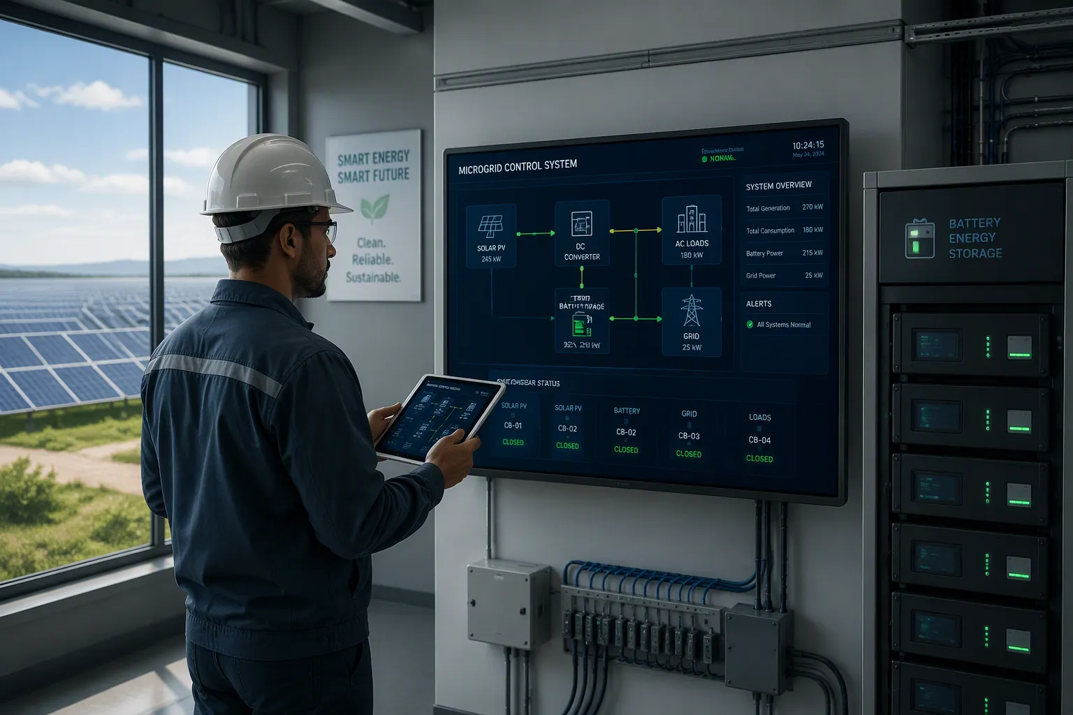
You design solar-storage integration for a telecom site in four steps. First, define priority-access rules. Second, size generation and storage to those rules. Third, engineer the switching controls. Fourth, validate compliance and cost.
Requirements: set the dispatch policy.
Architecture and sizing: match solar and batteries to site load.
Switching: build seamless mode transitions.
Compliance and cost: confirm standards and budget.
This guide serves telecom power engineers and system designers working with Telecom Power Systems. The goal is a site that maximizes renewable energy use, keeps uptime, and moves cleanly between grid, islanded, and hybrid modes. Solar and storage join the rectifier platform, so smart microgrids need coordinated control. ESTEL's Telecom Power System, a 19-inch rack-mount rectifier platform, works as a reference example for these integrations.
Key Takeaways
Set clear priority-access rules first. This means solar power goes first, then battery, then grid. These rules guide all design choices.
Size solar panels and batteries based on your site's actual energy use. Measure real load data to avoid oversizing or undersizing.
Design smooth switching between grid, islanded, and hybrid modes. Test each transition to keep your site running without interruptions.
Check compliance with local standards early. Confirm certifications for inverters and batteries to avoid delays.
Balance upfront costs with long-term savings. Compare battery types on lifetime cost, not just initial price.
Renewable Energy Priority-Access Rules
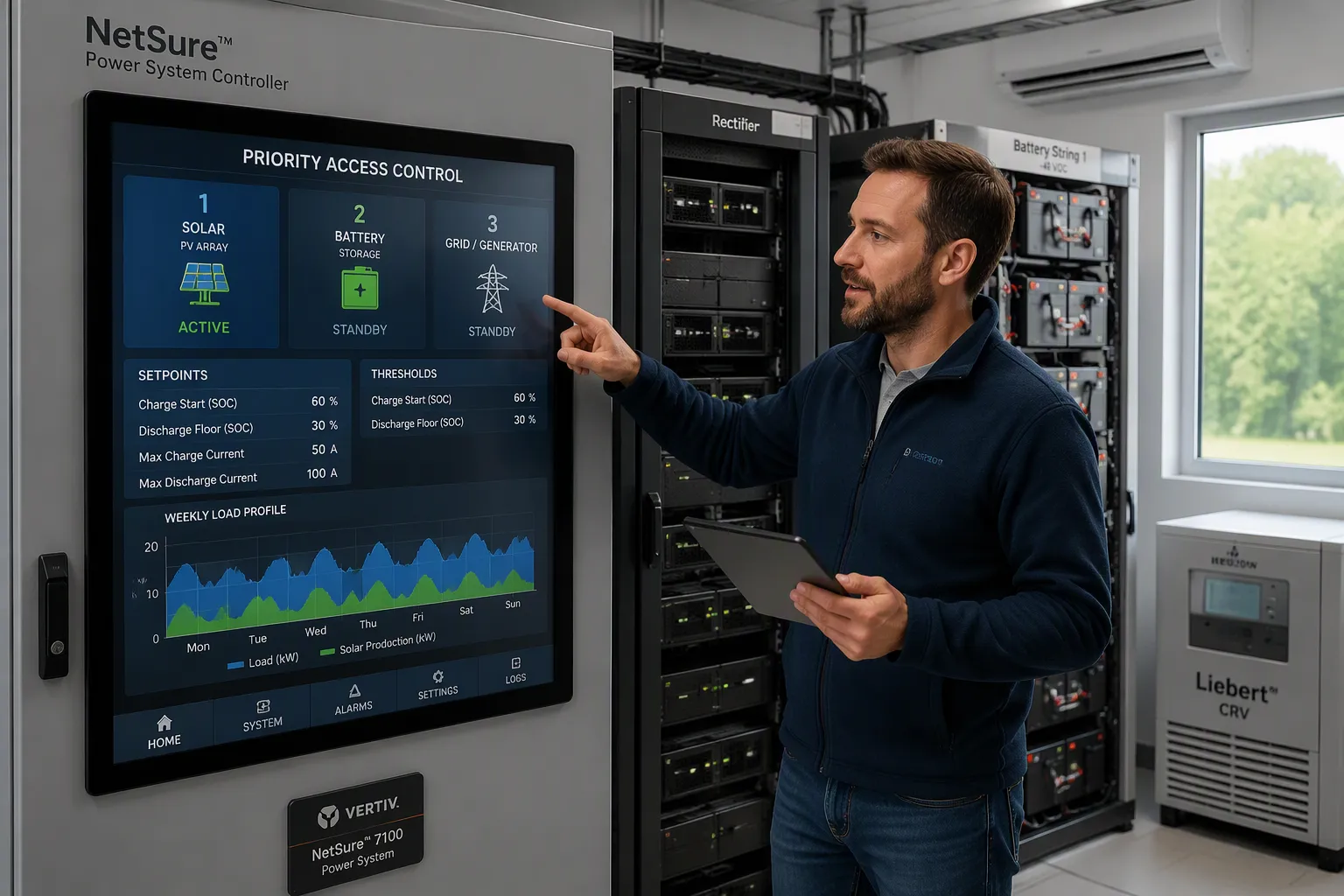
Priority-access rules turn a policy statement into numbers a controller can act on. The policy is simple: solar first, storage second, grid or generator last. The engineering work lies in translating that order into setpoints for every operating condition at your site.
Map Rules to Site Load Profiles
Start with a load profile, not with hardware. Log the DC demand of the base station, the rectifier bank, and the cooling equipment over a full week. Separate the constant loads from the cyclic ones. Rectifier output at a typical macro site swings with traffic, and cooling demand tracks ambient temperature rather than traffic.
Next, overlay the solar production window for your location. A site with strong midday yield and a modest base station load can absorb most renewable energy directly. A site with heavy cooling load in the afternoon needs a different balance. Match the two curves and you see the gap that storage must cover.
This profile also shapes your renewable energy integration strategy. Sites with a narrow solar window lean on battery autonomy. Sites with a wide window can run a smaller battery and export or curtail the surplus. Either way, the profile tells you where renewable energy sources deliver the most value and where they fall short.
Set Dispatch Setpoints
Convert the priority order into explicit thresholds. A workable starting logic looks like this:
Solar covers load first, up to available production.
Surplus solar charges the battery until it reaches its charge limit.
The battery discharges only when solar falls below load.
The grid or generator picks up the remainder.
Express each step as a setpoint: a charge-start threshold, a discharge floor tied to depth-of-discharge limits, and a grid-start threshold. Keep the grid-start threshold above the discharge floor so the battery never empties before backup takes over.
Time-of-day scheduling adds a second layer. You can shift battery charging into the strongest production hours and reserve capacity for the evening peak. Forecast-based dispatch goes further. A controller that reads a production forecast can pre-charge before a cloudy day and hold reserve for a predicted shortfall. This is where energy management software earns its place in smart microgrids.
Setpoints need review as seasons change. Recheck the profile quarterly and adjust thresholds to the new production window. Document each setpoint and the reasoning behind it, so commissioning and later optimization stay consistent.
Architect Solar-Storage for Telecom Power Systems
Choose Integration Topology
You have two topology choices for solar-storage integration: DC-coupled and AC-coupled. Each fits different site conditions. The table below compares them on technical performance.
Technical Metric | DC-Coupled | AC-Coupled |
|---|---|---|
Round-trip efficiency | ~85%–90% | |
Conversion stages | Two | Four |
Annual conversion losses | Lower | ~8%–12% higher |
Maintenance points | ~20%–30% lower | More components, modular replacement |
DC-coupled designs route solar DC power straight to the battery through a charge controller or hybrid inverter. This eliminates one full AC-DC-AC cycle and raises round-trip efficiency. AC-coupled designs use separate solar and battery power inverters on a shared AC bus. They add conversion steps but offer easier retrofitting and independent component replacement.
Your rectifier platform anchors either topology. ESTEL's Telecom Power System is a 19-inch rack-mount unit with 90–300 Vac input, natural cooling, and multiple communication ports. Those ports let you link solar and storage controllers to the rectifier for coordinated energy management.
Size Solar and Storage
Sizing follows a fixed sequence. Work through these steps for every site:
Measure actual site load from rectifier data or smart meters. Nameplate power overstates equipment load.
Compute daily energy use in kWh. Annual consumption equals average load × 24 × 365.
Estimate solar yield by location. Regional planning ranges span 900–1,900 kWh/kWp/year.
Size PV capacity as daily energy demand ÷ peak sun hours ÷ system efficiency.
Size battery capacity as critical load × backup hours ÷ usable depth of discharge ÷ system efficiency. A 20 kWh/day load at 90% DoD needs at least 22.2 kWh of storage.
Set autonomy — the days the site runs without sun.
Choose 48V as your system voltage for most telecom sites. Higher voltage cuts balance-of-system costs and allows longer wire runs. Validate every figure with site-specific solar resource data before you commit.
For telecom sites, solar and other renewable energy sources combined with intelligent battery storage can reduce grid dependence, improve resilience, and lower the total cost of powering the site.
Smart Microgrid Switching and Interoperable Smart Microgrids
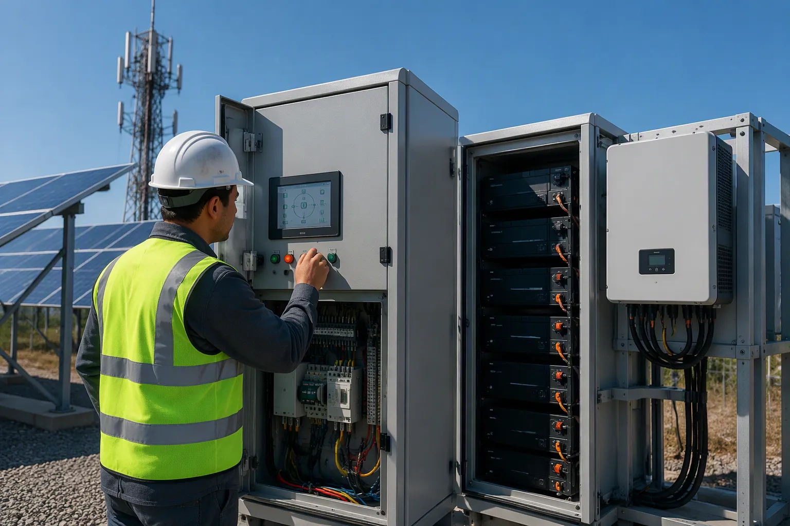
A telecom site with solar and storage runs in one of three modes. In grid-connected mode, the rectifiers draw from the utility and the controller follows your priority-access setpoints. In islanded mode, the site disconnects from the grid and the solar microgrid carries the load alone. Hybrid mode blends the two, with the battery buffering short grid outages while the site stays tied to the utility. The switching logic decides which mode applies, and that logic must act before the load sees a voltage dip.
Design Seamless Mode Transitions
Seamless transitions depend on detection speed and pre-set responses. The controller watches grid voltage and frequency, then commands a transfer when either drifts outside your threshold. Smart inverter control strategies let the inverter ride through brief disturbances instead of tripping. The energy management system then rebalances solar, storage, and rectifier output during the transfer. A well-tuned sequence holds the DC bus steady, so the base station never reboots.
Smart microgrid controls also govern the return path. When the grid recovers, the controller checks voltage and phase, then reconnects without a hard switchover. You should test each transition path at commissioning, including a forced islanding event. AI optimization is an emerging trend here. Learning-based controllers can predict load and production patterns, then adjust switching thresholds ahead of an event. Treat these tools as aids to your rule set, not replacements for it.
Coordinate Controls and Protection
Protection coordination keeps a fault in one branch from collapsing the whole site. Your microgrid controllers must share trip signals, and your protection settings must match the inverter's fault current limits. Interoperable smart microgrids need more than copper and relays. They need a shared language across devices from different vendors.
Smart grid communication and networking rest on published standards. The table below lists the main families you will meet in microgrid integration work.
Standards Body | Key Standards / Protocols | Scope and Relevance |
|---|---|---|
IEC | IEC 61850 series (7-1, 7-2, 8-2) | Communication networks for power utility automation; enables interoperability between substation devices |
IEEE | IEEE 1815 (DNP3) | Distributed Network Protocol for electric power systems communications |
IEEE | IEEE 2030 | Smart grid interoperability reference model (SGIRM) |
ANSI | ANSI C12.22 | Protocol for interfacing data communication networks |
MultiSpeak | Versions 1.1–5.0 | Enterprise application interoperability using common data semantics |
For distributed energy resource integration, IEC 61850-7-420 and IEC 61850-90-7 define the information model and the use cases for exchanging data between DERs and supervisory units. IEC 61850-8-1 with MMS governs traffic inside the microgrid LAN, linking DER controllers and battery management systems to the microgrid controller. IEC 61850-8-2 with DDS covers wide-area traffic between the site controller and the utility. Logical nodes define the interaction sequences: active power setpoints via DRCT, status via ZINV and DRCS, connect and disconnect via CSWI, and service duration via DOPM.
Data compatibility matters as much as the protocol list. Peers should connect directly without a central server, so a monitoring failure does not stop electrical exchange. Protocol converters help bridge old and new systems, but they can misread data. Plan your microgrid communication system for migration, and confirm that new devices join the existing infrastructure cleanly. Good communication design for energy management pays off in fewer commissioning surprises.
Microgrid Integration Compliance and Cost
Meet Interconnection Standards
Compliance starts with the grid interface. Your site must meet the local interconnection rules for anti-islanding, voltage and frequency ride-through, and power quality. The inverter or PCS carries most of that burden, so confirm its certification before you buy. Fire and electrical safety standards such as UL 9540 and UL 1973, plus NFPA 855 for installation, shape the enclosure and spacing you need. Telecom power standards and IEC 61427 and 62257 cover battery performance and rural electrification systems. EMC and EMI rules add filters and shielding costs, yet regulators often make them mandatory.
Document every certificate at the design stage. A missing listing can stall commissioning for weeks. Keep the compliance file with your setpoint records, so later audits and upgrades move faster.
Balance Capital and Operating Costs
Three cost drivers dominate the budget: battery chemistry, power inverters, and the cabinet. Compare chemistries on lifetime cost, not headline price. Lead-acid costs less upfront, yet it offers fewer deep cycles and needs frequent replacement. Lithium-ion, especially LFP, costs more initially and delivers deeper cycling and longer service intervals. BloombergNEF put the 2024 average lithium-ion pack price near $115/kWh. Installed energy storage solutions typically run $280–$580/kWh, or $180–$300/kWh for containerized systems of 100 kWh or more.
Enclosure choice follows site conditions. The IP or NEMA rating, thermal management, corrosion protection, and theft protection all raise cost, with cabinets ranging from about $500 to $5,000 or more. Cabinets last 10–20 years; batteries are replaced every 5–10 years. ESTEL's outdoor battery cabinets and lithium iron phosphate batteries suit remote sites that need durable enclosures and long-cycle storage.
Treat the design as a repeatable checklist for any site:
Define priority-access rules.
Size solar and storage to those rules.
Engineer switching controls.
Validate compliance and cost.
Priority access is a control-policy decision you make before sizing hardware. Seamless switching depends on coordinated controls and protection across your telecom power systems.
Start with a site load and renewable energy resource assessment. Then iterate sizing and switching design against regulatory and cost limits. Integrated platforms such as ESTEL's Telecom Power System can simplify commissioning and ongoing energy management, helping smart microgrids balance renewable energy sources, storage, and grid supply through careful integration work.
FAQ
What should you define before choosing solar panels or batteries?
Set your priority-access rules first. Decide the order — solar, then storage, then grid or generator — and turn that order into charge, discharge, and grid-start thresholds. Sizing follows those setpoints. Hardware chosen before the policy often ends up oversized or unable to follow the dispatch logic you need.
How do you decide between DC-coupled and AC-coupled integration?
Compare conversion stages and site conditions. DC-coupled designs skip one AC-DC-AC cycle and reach roughly 89%–94% round-trip efficiency. AC-coupled designs add conversion steps but retrofit more easily and allow independent component replacement. Match the choice to your rectifier platform and maintenance access, not to a single efficiency number.
How much battery capacity does a telecom site need?
Size storage from critical load, backup hours, usable depth of discharge, and system efficiency. A 20 kWh/day load at 90% depth of discharge needs at least 22.2 kWh of storage. Confirm the figure against your own load profile and the autonomy days your site requires.
Which standards apply to microgrid switching and interconnection?
Check local interconnection rules for anti-islanding, ride-through, and power quality first. Safety standards such as UL 9540, UL 1973, and NFPA 855 shape the enclosure and spacing. For device communication, IEC 61850 series and IEEE 2030 support interoperable smart microgrids across vendors.
Can one rectifier platform support both solar and storage control?
Yes, if it offers the right interfaces. ESTEL's Telecom Power System is a 19-inch rack-mount unit with 90–300 Vac input, natural cooling, and multiple communication ports. Those ports let you connect solar and storage controllers for coordinated dispatch. Confirm protocol compatibility with each controller before commissioning.
See Also
Solar Energy Storage Power System Designed for Telecom Cabinets
ESTEL Smart Microgrid Integrated Energy Storage System for Telecom Cabinets
Grid Connected Solar Inverter and Battery System for Telecom Cabinets
Calculation Methods for Telecom Cabinet Power Systems and Telecom Batteries
Energy Storage Batteries Specifically Designed for ESTEL Telecom Cabinets
CALL US DIRECTLY
86-13752765943
3A-8, SHUIWAN 1979 SQUARE (PHASE II), NO.111, TAIZI ROAD,SHUIWAN COMMUNITY, ZHAOSHANG STREET, NANSHAN DISTRICT, SHENZHEN, GUANGDONG, CHINA
