How Telecom Rectifier Systems Achieve High Power Factor and Low Harmonic Suppression to Purify the Grid Environment and Reduce Energy Losses


Telecom rectifier systems achieve a high power factor and low harmonic suppression through active power factor correction front-ends, advanced digital control, and multi-stage harmonic filtering. A communication power rectifier module shapes its input current to follow the input voltage, so the pfc stage draws nearly sinusoidal current from the grid. This design cuts harmonic distortion and keeps harmonics low.
Why does this matter to you? Cleaner grid current and voltage mean less reactive circulation, lower conductor heating, and reduced energy waste across the network. Better power quality also protects sensitive loads and supports a clean and stable power supply.
Each rectifier power module must balance efficiency, cost, and size. The techniques behind these results and the trade-offs they impose deserve close attention.
Key Takeaways
Active power factor correction shapes input current to follow voltage, cutting harmonics and boosting power factor.
Digital control improves precision and adapts to load changes, keeping distortion low across the range.
Harmonic filters remove leftover distortion, protecting the grid and reducing energy waste.
High power factor and low harmonics cut energy losses, lower cooling needs, and extend equipment life.
Match filtering to your load and check harmonic standards to balance performance and cost.
Why Power Factor and Harmonics Matter
Power factor and THD defined
Power factor is the ratio of real power to apparent power. A value near one means the load converts most of the supplied current into useful work. A low value means the load pulls extra current that does no work but still heats the wiring.
Total harmonic distortion describes how far the input current departs from a clean sine wave. You will also see it written as current THD. A communication power rectifier module with a well-designed pfc stage keeps this number low, so the current it draws stays close to a pure sine shape.
Grid purity and energy waste
Poor power factor and harmonic currents degrade the power grid in several ways. They distort the voltage waveform, heat conductors and neutrals, and waste energy along the return path. Studies of facility-level data put that waste at roughly 3 to 8 percent of kWh consumed.
The payoff from correcting these problems is measurable. One telecom central office consuming 6 GWh per year started at a power factor of 0.92. After correction, the site reached 0.99 and cut energy use by 13.3 percent, with amperage falling 11 to 32 percent.
Metric | Value |
|---|---|
Facility type | Telecom Central Office |
Facility energy consumption | 6 GWh/yr |
Starting power factor | 0.92 |
Energy savings achieved | 13.3% |
Power factor improvement | 92% → 99% |
Amperage reduction | 11–32% |
These gains matter because every kilowatt of wasted current must be generated, transmitted, and cooled. Cleaner current flow improves power quality across the network and lowers the burden on every upstream component.
Core Techniques in Telecom Rectifier Systems
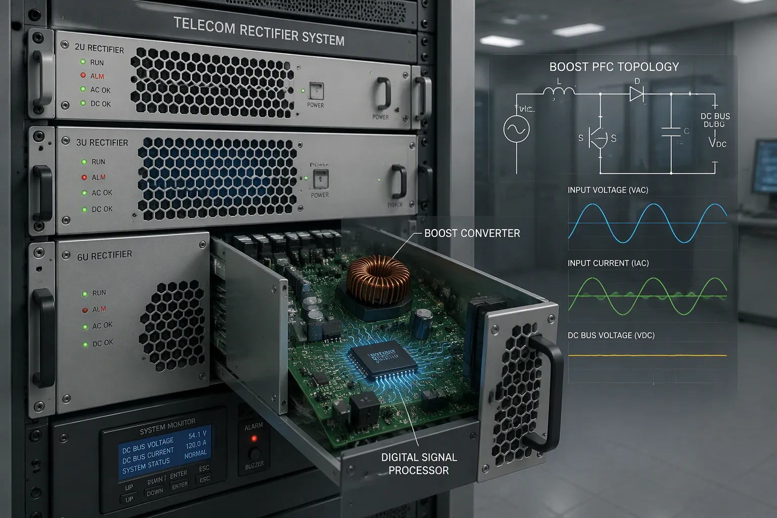
Active PFC in Telecom Rectifier Systems
Active power factor correction sits at the heart of modern telecom rectifier systems. A boost-type front-end takes the rectified AC input and lifts it to a stable DC bus voltage. The pfc circuit then controls the switching device so the input current waveform tracks the shape of the input voltage. You get a clean current draw from the grid and very little reactive circulation.
This approach differs sharply from passive designs. A passive front-end relies on large inductors and capacitors. It cannot fully reshape the current. An active pfc stage forces the current to follow the voltage on every switching cycle. The result is a low total harmonic distortion and a power factor close to one.
The pfc circuit also stabilizes the DC bus for the downstream DC-DC stage. That stability supports consistent ac-to-dc conversion across wide input ranges. Designers favor boost topology for its continuous input current and low harmonic currents. The boost inductor carries a continuous current, so the ripple stays small and the filter size drops. These traits suit telecom loads well.
ESTEL's Telecom Rectifier System applies this principle in a modular design. The unit delivers efficiency exceeding 96% and accepts flexible AC220V/380VAC input. Each rectifier power module fits standard 19-inch racks in 6U, 3U, or 2U form factors. The modular layout lets you scale output current from 6A to 125A as site demand grows, and you can swap a single module without taking the rack offline.
Advanced digital control methods
Digital control turns a good pfc stage into a precise one. A digital signal processor runs the control loop and samples voltage and current many times per cycle. Current-mode control regulates the inductor current directly. This inner loop responds fast to line and load changes. Feed-forward compensation predicts disturbances before they reach the output. The controller adjusts the duty cycle early and keeps the current clean. The loop runs at a high switching frequency, so the correction happens well above the line frequency.
These methods cut harmonic distortion further than analog control alone. You can also update firmware to tune performance without changing hardware. That flexibility helps telecom rectifier systems meet tight power quality targets and harmonic limits across different grids. A second power factor correction refinement comes from adaptive gain scheduling. The controller changes its response as the load moves from light to full. This scheduling keeps the front-end stable across the full load range.
Digital control also improves conversion efficiency at light load. The controller can disable unnecessary switching and reduce losses. A communication power rectifier module benefits from this smart behavior. The rectifier power module also shares load evenly through a digital bus. A second communication power rectifier module in the same rack follows the same control scheme.
Together, active power factor correction and digital control form the core of clean power conversion. They suppress harmonics at the source and keep harmonics out of the neutral. They also prepare the current for the harmonic filtering stage that follows. Suppliers of modular rectifier solutions now treat these techniques as standard practice. A well-tuned communication power rectifier module delivers stable DC48V output with low distortion. Passive harmonic filters and active harmonic filters then handle any residual harmonic content. That combination keeps the grid interface clean and the operating cost low.
Filtering and Harmonic Suppression
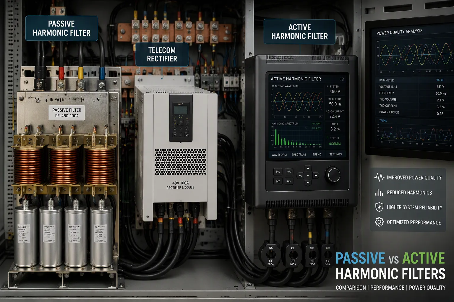
A well-tuned front-end suppresses most distortion at the source. Residual content still reaches the grid, so the system adds harmonic filtering as a second line of defense. You can choose passive or active approaches, and each fits a different role.
Passive harmonic filters
A passive harmonic filter connects in series with the load. It creates a low-impedance channel that diverts harmonic currents away from the power system. The diverted current circulates inside the filter instead of flowing back toward the transformer. You typically install one filter per harmonic-producing load. This one-to-one pairing keeps the design simple and predictable.
Passive units suit sites with a stable load profile and a known harmonic spectrum. They need no control power and no tuning loop. Their fixed components handle the dominant orders well. A communication power rectifier module often pairs with a passive stage when the site runs at a steady current. The filter then absorbs the remaining harmonic content and protects the neutral.
The trade-off is inflexibility. A passive harmonic filter cannot adapt when the load changes or new equipment joins the bus. It also adds weight and bulk to the rack. You must size it for the worst case, so light-load operation wastes some capacity.
Active harmonic filters
An active harmonic filter works like noise-canceling headphones for the power system. It senses the distortion on the line and injects equal-and-opposite frequencies. The two waveforms cancel, and the grid sees a cleaner current. This closed-loop action adapts to changing loads in real time.
Active harmonic filtering handles multiple loads from one unit. You gain flexibility that a fixed passive stage cannot offer. The device also helps reduce system losses, though energy savings is not its primary purpose. Treat loss reduction as a bonus, not the reason to buy.
Active units cost more and need control power. They shine where the load mix shifts or where space is tight. A rectifier power module in a dense rack benefits from this compact, adaptive approach.
SCR technology offers another option for superior harmonic suppression. It delivers measurable total harmonic distortion reduction and suits demanding sites. Pair it with advanced harmonic filtering when you need the cleanest possible interface.
Both paths support harmonic mitigation, and the right choice depends on your load. Passive stages reward stable, predictable sites. Active stages reward flexibility. Many designs combine them, so harmonic distortion stays low across the full operating range. That layered approach protects power quality and keeps the grid interface clean.
How ESTEL Telecom Rectifier Systems Reduce Energy Losses
Cutting conduction and switching losses
A high power factor means the current you draw stays in phase with the voltage. That alignment shrinks the reactive current that circulates without doing useful work. Less reactive circulation means less current flows through cables, breakers, and transformers. Conduction losses fall as a direct result, because resistive heating rises with the square of the current.
Low harmonic distortion adds a second gain. Harmonic currents heat neutral conductors and upstream windings even when they deliver no real power. Strong harmonic filtering at the front end keeps those currents out of the grid. Your neutral stays cooler, and the whole distribution path carries less wasted current.
Switching losses also matter inside the rack. A high-efficiency rectifier architecture uses fast switching devices and soft-switching techniques to trim turn-on and turn-off losses. The pfc stage and the DC-DC stage each contribute. Careful gate control and low-loss magnetics keep ac-to-dc conversion efficient across the load range.
System-level efficiency gains
ESTEL's Telecom Rectifier System shows how these practices translate into real numbers. The unit delivers efficiency exceeding 96%, with a steady DC48V output and current options from 6A to 125A. You can mount it in 6U, 3U, or 2U designs for standard 19-inch racks. Each rectifier power module fits the same rack, so you scale capacity without redesigning the site.
System-level benefit | Reported value or effect |
|---|---|
Peak rectifier efficiency | Greater than 96% |
Power factor | ≥ 0.99 |
Total harmonic distortion | Strictly controlled at a low level |
Cooling load | Reduced air-conditioning usage |
Part-load performance | Good efficiency under partial load |
Standby consumption | Low, cutting waste at unmanned sites |
Standards compliance | Meets IEEE harmonic standards |
These gains compound across a network. Lower heat dissipation eases the cooling load, and that saving supports energy-efficient telecom infrastructure. A communication power rectifier module that holds good conversion efficiency at part load suits most telecom sites, which rarely run at full capacity. Low standby draw protects unmanned remote stations. Treat ESTEL as one example of a supplier applying these design practices; many vendors now build similar modules.
Design Considerations for Compliance and Cost
Meeting harmonic standards
Compliance starts with the right reference. IEEE 519 sets limits on harmonic currents that a load may inject into the grid, and it ties those limits to the short-circuit ratio at the point of common coupling. Telecom equipment also faces local THD limits, so you should confirm the target for your site before you size any stage. A design that meets IEEE 519 at one site may fail at another with a weaker supply.
Your pfc circuit does most of the compliance work. It holds total harmonic distortion low at the source, so downstream stages only clean up residual content. Add harmonic filtering where the load mix is complex or the supply is soft. Document the measured harmonic distortion against the standard, and keep the test record with the site file.
Balancing performance and cost
Every choice trades one benefit against another. A boost pfc front-end raises power factor correction performance and conversion efficiency, yet it adds control complexity and cost. Passive harmonic filters cost less up front and suit steady loads, but they cannot adapt when the load shifts. Active harmonic filters adapt well and save space, yet they need control power and a higher budget.
Match the option to the site. Stable, predictable loads reward a passive stage. Shifting loads and dense racks reward active harmonic filtering. Where the cleanest interface matters, SCR technology with advanced harmonic filtering delivers strong suppression. Weigh size and reliability alongside price, because a compact module that fails often costs more than a larger, proven one.
A communication power rectifier module with good part-load efficiency pays back over years. A communication power rectifier module built to ISO9001 quality control reduces rework and downtime. ESTEL applies these practices across its line, and each rectifier power module ships against international standards. Check the harmonic currents your design injects, protect power quality at the coupling point, and let the numbers guide the trade-off.
Active power factor correction, advanced digital control, and harmonic filtering work as one chain. The pfc front-end shapes the input current, the control loop keeps it precise, and the filters remove what remains. Together they raise power factor and suppress harmonics, which purifies the grid and cuts losses.
Results depend on your choices. Match the technique to the load and weigh cost against performance. ESTEL applies these principles across its telecom rectifier systems. Each communication power rectifier module ships with efficiency above 96%, and each rectifier power module keeps harmonic distortion low. Expect tighter limits ahead. A communication power rectifier module with strong conversion efficiency and clean power quality will keep your site ready.
FAQ
What power factor can a telecom rectifier system achieve?
A well-designed pfc front-end pushes the power factor close to one. ESTEL's Telecom Rectifier System reaches a power factor of at least 0.99. That near-unity value means the load converts most supplied current into useful work, and reactive circulation stays small.
How does harmonic filtering keep the grid clean?
Harmonic filtering removes residual distortion that the front-end leaves behind. A passive stage diverts harmonic currents away from the system. An active stage injects equal-and-opposite frequencies to cancel them. Either way, the grid sees a cleaner current and a more stable voltage waveform.
Why does low harmonic distortion cut energy losses?
Harmonic currents heat neutral conductors and upstream windings without delivering real power. Suppressing harmonics keeps those currents out of the distribution path. Your conductors run cooler, and every upstream component carries less wasted current. The savings compound across a full network.
What should you check before choosing a rectifier power module?
Confirm the harmonic limits your site must meet, such as IEEE 519. Check efficiency at part load, because telecom sites rarely run at full capacity. Verify the input voltage range and rack size. A communication power rectifier module built to ISO9001 quality control reduces rework and downtime.
How do modular designs support scalability?
A communication power rectifier module fits a standard 19-inch rack in 6U, 3U, or 2U form. You add modules as demand grows and swap one without taking the rack offline. Output current scales from 6A to 125A, and efficiency stays above 96% across the range.
See Also
Essential Features You Should Know About Telecom Power Supplies
How to Guarantee Reliable Power Supply for Telecom Cabinets
Solar Energy Storage Power System Designed for Telecom Cabinets
Beginner's Guide to Understanding Telecom Power Supply Systems
Grid-Connected Solar Inverter and Battery System for Telecom Cabinets
CALL US DIRECTLY
86-13752765943
3A-8, SHUIWAN 1979 SQUARE (PHASE II), NO.111, TAIZI ROAD,SHUIWAN COMMUNITY, ZHAOSHANG STREET, NANSHAN DISTRICT, SHENZHEN, GUANGDONG, CHINA
