How to Design a Compact Emergency Communication Vehicle Kit with Quick-Deploy Brackets for Telecom Power Systems

When disasters strike, rapid-deploy emergency communication kits restore telecom services fast. You need a compact vehicle kit that sets up quickly and works with existing telecom power systems. This guide walks you through five key design steps: assess needs, select compact components, design quick-deploy brackets, integrate with telecom power, and test. Portability, speed of deployment, and power compatibility drive every decision. ESTEL-grade materials and components support durability and reliability in harsh field conditions. A compact, flexible mobile command vehicle can establish rapid control of critical incidents and coordinate teams effectively.
Key Takeaways
Assess your communication needs and power sources first to choose the right components.
Select compact, durable gear like mesh radios and lithium iron phosphate batteries for reliable performance.
Design quick-deploy brackets with tool-free features for fast setup in any condition.
Integrate your kit with existing telecom power systems using matching connectors and protection circuits.
Test your kit with timed drills and environmental tests to ensure speed and reliability.
Assessing Communication and Telecom Power Systems
Define the emergency communication mission and the power environment the kit will face. You need to know where the kit will operate and which power sources you can tap. That knowledge shapes component selection, bracket dimensions, and cable choices.
Deployment Scenarios and Coverage
Emergency communication kits serve remote roads, mountain passes, disaster zones, and temporary command posts. The most common settings are areas where permanent telecom networks are damaged or unavailable. Mobile cell towers provide temporary service during outages, while emergency vehicles supply mobile command and communication for disaster response.
Consider these threats:
Hurricanes disrupt fiber and cellular service in coastal areas, requiring rapid-deploy platforms.
Wildfires damage terrestrial networks, demanding immediate backup connectivity.
Floods destroy permanent infrastructure, so mobile command vehicles must deploy quickly.
Infrastructure failures leave permanent networks unavailable, requiring temporary communication vehicles.
In a coastal county hurricane scenario, you can stage a compact vehicle at an emergency operations center in minutes. It provides satellite-backed Wi-Fi for command staff, responders, and essential personnel. That speed depends on knowing your coverage area and user count.
Telecom Power Inputs and Voltage
Next, map the telecom power inputs you expect to find. Telecom Power Systems vary by voltage range, connector type, and current. Know the input voltage range the kit can accept, the output voltage your equipment needs, and the maximum current draw. For example, a rectifier system might deliver -42 to -58 Vdc output and up to 90 A. Match the kit's DC interface to those parameters so it plugs directly into an existing power system.
Design for plug-and-play operation. Measure voltage at the vehicle's power inlet and at the telecom cabinet. Check output stability during generator transfer. Use components that accept a wide AC input range, such as 90-280 Vac, to handle unstable power.
ESTEL serves telecom operators and infrastructure providers in challenging outdoor environments. That experience gives you access to rugged components. Choose power modules with wide input ranges and multiple communication ports. This ensures your compact kit integrates with existing Telecom Power Systems and delivers reliable power.
Selecting Compact Components
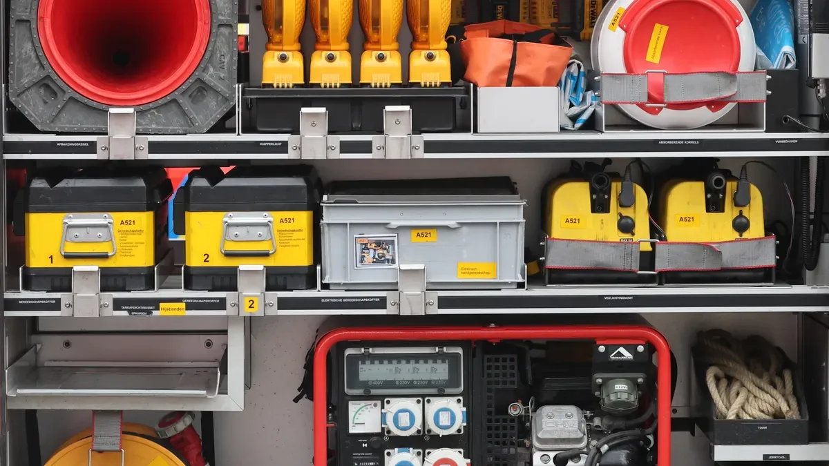
Component selection must balance portability, durability, and electrical compatibility. Your compact emergency kit has limited space, yet it must survive harsh field conditions and connect cleanly to existing Telecom Power Systems. Start with the communication gear, then match power components to that gear.
Portable Communication Equipment
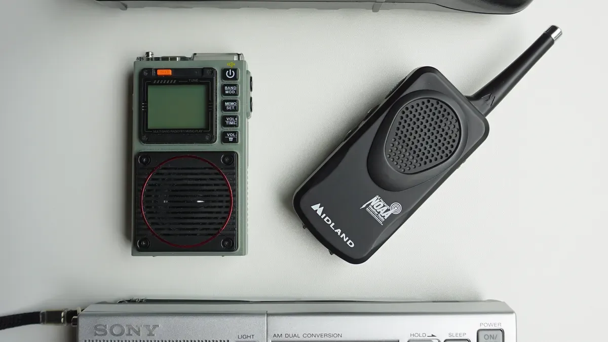
Choose radios that establish secure, non-line-of-sight wireless links on demand. Broadband and narrowband systems serve different roles. The Hytera E-pack200, a DMR narrowband radio, creates an infrastructure-free, push-to-start ad-hoc network. It can even repeat calls over LTE when a SIM and coverage exist. The TETRA E-Pack 100 offers a similar infrastructure-free ad-hoc network and interoperates with TETRA handsets in direct mode. Both use authentication, software and hardware encryption, and whitelisting to protect the data path.
For high-throughput data, consider the Hytera E-mesh580P broadband mesh radio. This backpack-portable unit auto-forms a broadband network when powered up. It supports up to 32 peer-to-peer nodes, with single-hop throughput up to 100 Mbps and eight-hop throughput greater than 16 Mbps. Live video and large data files move quickly across this network. These radios need no carrier infrastructure or IP backhaul, so they operate when public mobile networks fail.
Radio System | Category | Deployment Role |
|---|---|---|
Hytera E-pack200 | Narrowband | Push-to-start ad-hoc network |
TETRA E-Pack 100 | Narrowband | Interoperates with TETRA handsets |
Hytera E-mesh580P | Broadband | Auto-forming mesh, 32 nodes |
ESTEL Power Components
Power components must deliver high energy density in a small footprint. Use rectifier modules and lithium iron phosphate batteries. ESTEL's Delta rectifier modules achieve conversion efficiency greater than 98%. They also include predictive analytics and self-optimization, which outperform basic competitor modules. These ultra-modular designs fit neatly into compact vehicle trays.
For energy storage, lithium iron phosphate batteries provide the best density. The AER18650m2A2 cell, for example, delivers 5.76 Wh of energy with a specific energy of 133 Wh/kg and an energy density of 330 Wh/L. Its 2000-cycle life at 100% depth of discharge makes it a durable choice for repeated deployments. A 10-second pulse discharge rating of 18 A supports brief high-current loads from radios and network switches.
Batteries also restore power faster than traditional generators. Field operations during hurricane recovery show an 83% improvement in response times using advanced battery systems. They create instant microgrids for field hospitals and communication relays, and they enhance diesel generator efficiency by allowing generators to run near their optimal load.
ESTEL provides the full power train: telecom rectifier systems, power distribution cabinets, and lithium iron phosphate batteries. Choose modules that accept a wide input range and communicate with your monitoring system. That combination keeps your kit small, reliable, and ready to deploy.
Designing Quick-Deploy Brackets
Quick-deploy brackets form the mechanical backbone of your emergency communication vehicle kit. They must enable tool-free mounting and dismounting so one person can install radios, power modules, and batteries in the field without searching for wrenches or screwdrivers. Every second counts during a disaster response. A bracket that requires tools slows your deployment and risks lost hardware in dark, wet conditions.
Mechanical Features
Design brackets around four core mechanisms: spring-loaded pins, cam locks, guide rails, and captive fasteners. Spring-loaded pins let you push a component into place and hear an audible click. The pin seats itself in a drilled hole or notch, locking the module without any threaded connection. Cam locks rotate a lever that clamps the component against the bracket face. A quarter-turn engages or releases the lock. Guide rails align the component as you slide it in, preventing misalignment that could damage connectors. Captive fasteners stay attached to the bracket even when unfastened, so you never drop a screw into grass or gravel.
Combine these features for a smooth workflow. Slide the radio along its guide rail until the spring-loaded pin snaps into position. Turn the cam lock to secure the module against vibration. Reverse the sequence to remove the component. This tool-free approach reduces setup time and eliminates the risk of stripped threads or lost hardware.
Materials and Load-Bearing
Material selection determines how long your brackets survive in the field. Choose steel or aluminum with an anti-corrosion powder coating. This coating resists rust, salt spray, and chemical exposure. High ingress protection ratings, such as IP55 or higher, keep dust and water out of critical joints and locking mechanisms. A bracket with a high IP rating maintains smooth operation even after rain, mud, or blowing sand.
Load-bearing capacity matters as much as corrosion resistance. Calculate the total weight of each mounted component, then add a safety margin for vibration and shock. A bracket that holds a rectifier module must support that module's weight plus the dynamic forces of vehicle movement. Use thicker gauge metal at mounting points and reinforce corners with gussets or bends. Distribute weight across multiple attachment points rather than concentrating it on a single bolt.
Test every bracket design for vibration, shock, and repeated deployment cycles. Vibration testing simulates rough roads and engine harmonics. Shock testing replicates sudden impacts from potholes or off-road terrain. Repeated deployment cycles verify that locking mechanisms still engage smoothly after hundreds of install-and-remove operations. A bracket that fails after fifty cycles will fail when you need it most.
ESTEL's outdoor telecom cabinets and power systems use anti-corrosion powder coating and high ingress protection ratings. That same material philosophy applies to bracket design. Choose coatings and seals that match the harsh environments your vehicle kit will face. A bracket that looks strong on paper but corrodes after one rainy season wastes your investment and endangers your communication link.
Integrating with Telecom Power Systems
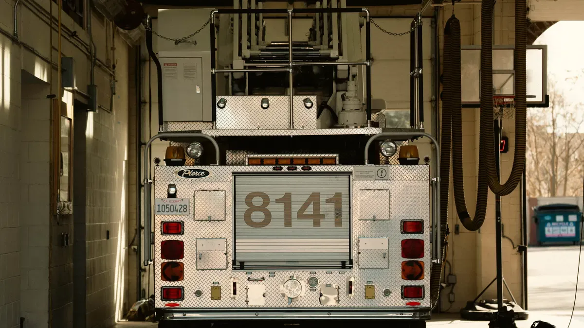
Your kit must integrate seamlessly with existing telecom power systems for plug-and-play operation. That means matching connectors, cables, and protection circuits before you mount a single bracket. A mismatched connector wastes deployment time. A missing protection circuit risks damaging both your equipment and the host power system.
Connectors, Cables, and Protection
Start by identifying the DC interface on the host system. Measure the output voltage and confirm the connector type. Telecom systems commonly use terminal blocks, Anderson connectors, or proprietary plugs. Match your kit's input connector to that interface. Keep spare adapter cables in the vehicle so you can connect to different systems without returning to base.
Cable sizing follows current draw and voltage drop. Use short, thick cables for high-current runs. A cable that is too thin wastes power as heat and reduces voltage at the load. Calculate voltage drop as current times resistance times cable length. Keep that drop within the input tolerance of your equipment.
Protection circuits prevent damage from reverse polarity, overcurrent, and surges. Install a DC circuit breaker or fuse rated slightly above your maximum current draw. Add a reverse-polarity diode or MOSFET to block accidental miswiring. Surge protection devices absorb voltage spikes from generator switching or lightning. These components cost little and prevent expensive failures in the field.
ESTEL Telecom Power System
The ESTEL GPE4890B Telecom Power System offers a suitable power solution for compact vehicle kits. Its specifications support flexible integration.
Parameter | Specification |
|---|---|
System/model | ESTEL GPE4890B Telecom Power System |
AC input voltage range | 90–280 Vac |
DC output voltage range | -42 to -58 Vdc (nominal 48 Vdc; typical -53.5 Vdc) |
Maximum output current | 90 A (at 176–280 Vac input; derated to 45 A at 90–175 Vac input) |
This system uses natural convection cooling. Ruggedized rectifiers reduce fan-related noise, maintenance, and cost. That design supports quiet, low-maintenance operation inside enclosed vehicle spaces. The system installs on a standard 19-inch rack or inside a cabinet. That flexibility fits space-constrained mobile communication units. Natural cooling also decreases the need for supplemental air conditioning and reduces energy use. In China, air conditioning accounts for about 40% of energy consumption in data centers. Natural cooling avoids that auxiliary load, which matters when vehicle power and space are limited.
Ensuring Seamless DC Power Interfacing and Secure Networking
Connect your kit's DC input to the host system output. Verify polarity before energizing. Confirm the output voltage falls within your equipment's input range. The ESTEL system delivers -42 to -58 Vdc, so your radios and network switches must accept that range. Use the system's multiple communication ports to link monitoring data back to your command post. Configure secure networking with authentication and encryption. Test the link under load to confirm stable data transfer. A seamless interface means your team spends time communicating, not troubleshooting power connections.
Testing and Validating the Kit
Testing must validate both reliability and speed of deployment. A kit that works perfectly but takes an hour to set up fails its mission. A kit that deploys in minutes but breaks under vibration also fails. You need to prove both qualities before the kit enters service.
Field Deployment Drills
Run timed deployment drills with the same people who will operate the kit in the field. Measure setup time from vehicle arrival to first communication link. Record each step: unloading, bracket mounting, cable connection, and power-up. Identify bottlenecks and eliminate them. A drill that reveals a slow step is a successful drill.
Set timing benchmarks based on your mission requirements. If your target is a fifteen-minute setup, practice until your team consistently meets that target. Repeat drills under different conditions: daylight, darkness, rain, and cold. Each drill builds muscle memory and exposes weaknesses in bracket design or cable routing. Track your times over multiple runs to confirm improvement.
Environmental and Electrical Testing
Environmental stress testing confirms the kit survives harsh conditions. Temperature and humidity tests verify that components operate across your expected range. Vibration and shock tests simulate rough roads and sudden impacts. Military standards provide proven test frameworks for mobile equipment.
Standard | Application in Mobile Kits |
|---|---|
MIL-STD-810H | Qualifies rack survival under shock, vibration, and environmental challenges |
MIL-S-901D | Military standard for rugged shock-tested products |
MIL-STD-167 | Military standard for vibration testing of shipboard equipment |
IP/NEMA ratings | Waterproofing and dust exclusion for harsh or open-air deployments |
Isolation mounts and shock pallets mitigate vibration for mobile deployments. Outdoor telecom enclosures commonly meet NEMA 3R through 4X, IP55, or IP65 ratings. Brackets and power components should match those protection levels.
Electrical testing covers voltage fluctuation, reverse polarity, and surge events. Confirm your kit operates across the full input range of the host Telecom Power Systems. Test with multiple power sources to verify compatibility. Validation should confirm the kit works with a range of Telecom Power Systems and emergency scenarios before you deploy it.
You now have a clear five-step path: assess needs, select compact components, design quick-deploy brackets, integrate with telecom power, and validate through testing. This process delivers portability, rapid setup, secure mounting, and broad compatibility with Telecom Power Systems.
Iterate on bracket designs and component choices using real field feedback. Reliable quick-deploy brackets and solid power integration form the backbone of any effective emergency communication vehicle kit. ESTEL provides durable outdoor telecom cabinets and power systems built for challenging environments.
FAQ
What voltage range should my emergency kit accept?
Your kit should accept the same range as your host telecom system. The ESTEL Telecom Power System accepts 90 to 280 Vac input. It outputs -42 to -58 Vdc. Verify your radios accept that DC range before you mount anything.
How fast can a quick-deploy bracket set up?
Tool-free mechanisms let one person mount and dismount modules in seconds. Spring-loaded pins, cam locks, guide rails, and captive fasteners remove manual tools. Field drills should measure actual setup time and set a target you meet consistently.
Why should I use lithium iron phosphate batteries?
They store more energy per weight than older chemistries and last about 2000 cycles at full depth of discharge. They pulse-power radios and switches during peak demand. Field operations during hurricane recovery showed 83% faster response times with advanced battery systems.
How do I protect my vehicle kit from power faults?
Add a DC circuit breaker or fuse rated slightly above maximum current draw. Include reverse-polarity protection and surge absorbers. Match connectors to the host system. This prevents damage from miswiring, overcurrent, and generator switching spikes.
What environmental tests should the kit pass?
Test for shock, vibration, temperature, and humidity. MIL-STD-810H qualifies racks for those conditions. Choose brackets with IP55 or higher to resist dust and water. Run repeated deployment cycles to confirm locks stay reliable.
See Also
Solar Power Storage System Designed For Telecom Cabinet Energy Needs
Methods To Guarantee Consistent Power Supply For Telecom Cabinet Operations
Essential Structural Design Guidelines For ESTEL Integrated Outdoor Telecom Cabinets
Building A Dependable Outdoor Communication Cabinet System For Every Climate
Requirements Of Outdoor Telecom Cabinets For Housing Communication Equipment
CALL US DIRECTLY
86-13752765943
3A-8, SHUIWAN 1979 SQUARE (PHASE II), NO.111, TAIZI ROAD,SHUIWAN COMMUNITY, ZHAOSHANG STREET, NANSHAN DISTRICT, SHENZHEN, GUANGDONG, CHINA
