Integration of Telecom Rectifier Systems into Unified Smart Park Power Networks


You achieve integration when your telecom rectifier systems connect to a unified smart park energy management control platform. This platform delivers real-time monitoring and control across your entire power infrastructure. Your core challenge is clear: how do you reduce costs and improve resilience without replacing existing rectifier equipment?
The answer lies in smart integration. You can transform your telecom rectifier system into an active participant in your energy management strategy. This approach delivers several outcomes: lower operating costs, stronger resilience, and future scalability. Your telecom power system becomes more efficient when rectifiers communicate with other assets. Energy management improves when every device works together. Integration also extends equipment life. You gain control without costly replacements. Your telecom power systems evolve into intelligent, responsive networks.
Key Takeaways
Integrate telecom rectifier systems into one smart park energy platform. This single action delivers real-time control, lower costs, stronger resilience.
Use gateway devices to connect older rectifiers with the unified control platform. This approach avoids the need for expensive equipment replacements.
Rectifiers become active energy assets. They coordinate with solar generation. They coordinate with battery storage. This coordination cuts peak demand.
Begin with a complete asset audit. Run a pilot microgrid project. This small step proves the value before full integration.
Choose open standards. Secure every data link. This step prepares your system for AI-driven optimization. It supports future scalability.
Unified Smart Park Energy Management Control Platform
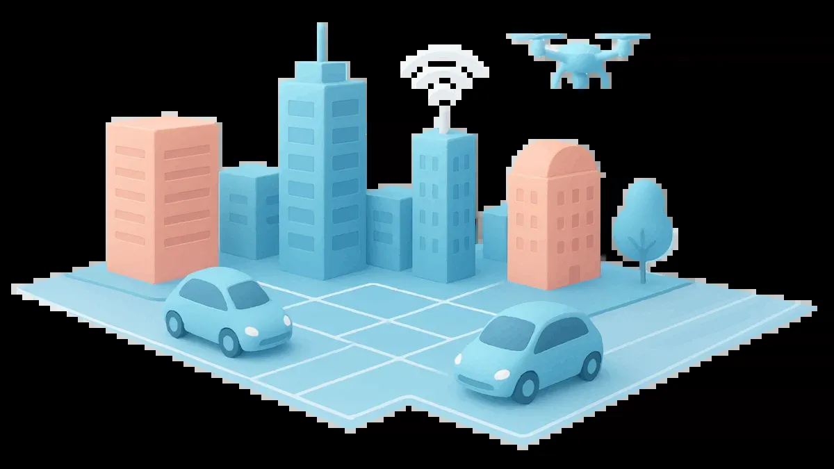
A unified smart park energy management control platform connects every energy asset in your park. Solar panels, battery storage, EV chargers, and telecom rectifier systems all report to one interface. You see real-time data from each device. You control each device from the same screen. This unified control platform eliminates the need to check separate systems for different equipment.
How Telecom Rectifier Systems Join the Platform
Your telecom rectifier system joins the platform through a gateway device. The gateway translates rectifier data into a common language. This process enables smart park energy management integration across all your equipment. You map each rectifier's communication protocol during setup. The gateway then sends this data to the unified control platform.
Direct integration answers your core question about cost and resilience. Your rectifiers stop being isolated telecom equipment. They become active participants in park energy management. The platform monitors rectifier output voltage, current, and battery status continuously. You receive alerts when performance drops. You adjust settings remotely without visiting the site.
Turning Rectifiers Into Active Energy Assets
Integration transforms your rectifiers into dispatchable energy assets. The platform coordinates rectifier operation with solar generation and battery storage. When solar production peaks, your rectifiers reduce output. When demand rises, they increase output. This coordination delivers smart energy management at the system level.
Your telecom power system gains new capabilities through this integration. The platform can shift rectifier load to match variable energy prices. It can charge batteries when rates are low. It can discharge batteries during peak demand periods. These actions lower your operating costs. They also extend battery life through optimized cycling. The unified control platform for multiple subsystems gives you one point of control. You gain visibility into every watt flowing through your park.
Why Integration Cuts Costs and Improves Resilience
The Cost of Siloed Telecom Power Systems
Siloed telecom power systems create hidden costs that drain your budget. Your team monitors rectifiers manually at each site. Technicians drive to remote locations just to read voltage and current values. This manual monitoring consumes labor hours and fuel. Duplicate maintenance compounds the problem. You service rectifiers separately from solar panels and batteries. Each system requires its own maintenance schedule and spare parts inventory. Underused battery capacity represents another wasted resource. Your batteries sit idle when they could store excess solar energy or provide grid services.
Integration eliminates these inefficiencies. A unified control platform connects every asset into one energy management system. You monitor all equipment from a central dashboard. Maintenance schedules align across systems. Battery capacity becomes a shared resource for the entire park. The payback period for smart energy management projects typically falls between 2.5 and 5.5 years. This range depends on local diesel cost, grid tariff, solar resource, battery capacity, installation cost, and incentive policy. Diesel-heavy off-grid sites achieve the fastest payback. Grid-connected sites depend more on electricity tariffs, demand charges, and tax incentives.
Region / Market | Typical Payback Period | Key Drivers |
|---|---|---|
Nigeria & diesel-heavy African markets | 2.5–4.5 years | High diesel cost, fuel logistics, weak grid, generator maintenance |
United States | 3–5.5 years | Grid tariff, resilience value, tax credit eligibility, depreciation |
Europe | 4–6 years | High electricity prices, carbon targets, energy efficiency requirements |
Middle East | 3–5 years | Strong solar irradiance, remote sites, national energy transition targets |
Resilience Gains From Real-Time Coordination
Real-time coordination transforms your telecom power system into a responsive network. The platform communicates with solar panels, storage batteries, and loads continuously. When energy prices spike, your rectifiers reduce output and batteries discharge. When prices drop, rectifiers charge batteries for later use. This coordination lowers peak demand charges significantly. Your energy management strategy adapts to changing conditions automatically.
Outages test your system's resilience. Real-time coordination keeps critical loads online during grid failures. The platform instantly switches to battery power when it detects an outage. Solar generation continues feeding your rectifiers and loads. Your unified control platforms manage this transition seamlessly. Telecom power systems with integrated energy management recover faster from disruptions. You maintain service continuity without manual intervention. The platform also predicts maintenance needs before failures occur. This predictive capability reduces downtime and extends equipment life.
Architecture for Telecom Rectifier Systems Integration
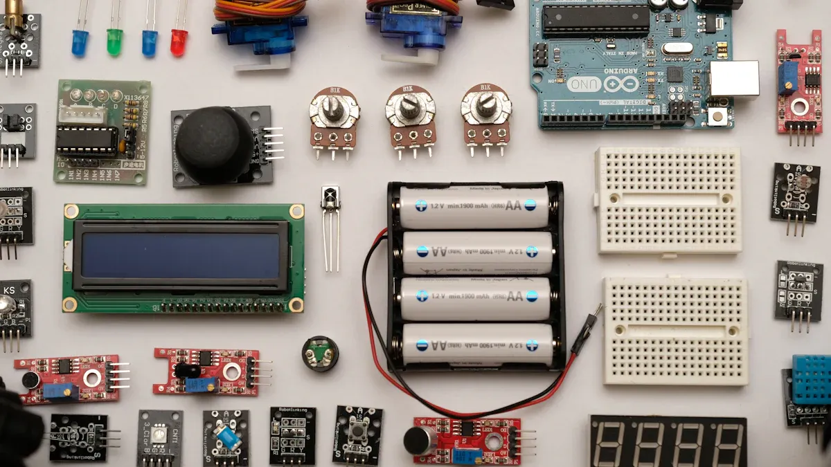
Smart park integration begins with a layered architecture. You need a structure that connects physical equipment to intelligent control. Modern platforms use an AIoT architecture. This design merges artificial intelligence with Internet of Things connectivity. It handles solar, storage, EV chargers, and telecom rectifier systems in one framework.
Device, Connectivity, Data, and Control Layers
The architecture contains several layers. The device layer holds physical assets. Rectifiers, batteries, and cooling units live here. Solar inverters join them. Each device plays a distinct role in your telecom power system. Sensors in this layer measure voltage, current, and temperature.
The connectivity layer links devices to the platform. Gateways translate device protocols into readable data. This layer enables subsystem integration: rectifiers, batteries, cooling. Without it, each device remains an island. Wired or industrial wireless routers provide stable links for permanent installations.
The data layer stores and normalizes the information flow. A time-series database records measurements from every device. It converts raw readings into standard units. Standardized data formats matter enormously. Successful telecom power system integration depends on clean data. Establish your data model early. Define every field, unit, and naming convention before deployment. This decision prevents costly rework.
The control layer executes your energy management decisions. It runs optimization algorithms for energy management and sends commands back to devices. It determines when batteries charge from the grid. It decides when batteries discharge to shave peak demand. This layer delivers the intelligence that distinguishes a unified platform architecture for telecom power system integration.
Your telecom rectifier system often uses a DC bus architecture. Your lithium battery management system must align with the DC bus voltage. The system monitors bus voltage continuously. It prevents overvoltage and undervoltage conditions. Charge and discharge limits require careful coordination. Mismatched rectifier output damages batteries. Your unified platform architecture must account for these electrical constraints from day one.
Data Flow and Control Logic for Rectifiers
Data flows upward from devices to the control layer. Commands flow downward from the control layer to your equipment. This bidirectional flow enables real-time coordination.
Consider a typical data journey. Your rectifier reports output current and bus voltage. The gateway translates the data into the standard format. The data layer stores the reading with a timestamp. The control layer compares the state against your energy management rules. It then sends a command to adjust output. The cycle completes quickly.
Control logic for rectifiers follows explicit rules. The system prioritizes solar energy when irradiance is high. Rectifiers, batteries, and cooling subsystems respond to the same logic. You define price-triggered load shifting thresholds. You set voltage limits for battery protection. You configure outage response sequences. Each rule specifies a condition and an action. This clarity prevents subsystem conflicts.
Your unified control platform coordinates subsystem actions. During peak prices, the system reduces load. Batteries supply the difference. During outages, the system switches to battery power. Solar recharges batteries when conditions allow. These actions improve resilience and reduce costs. Your unified control platforms repeat this cycle automatically. You monitor performance from one dashboard without manual intervention.
Good control logic respects equipment limits. The system tracks temperature and battery state of charge. It adjusts commands to prevent overload. This protection extends equipment life. It reduces maintenance costs. It keeps your telecom power system within safe operating parameters.
Smart Park Energy Management Integration of Telecom Rectifier Systems
The path from siloed rectifiers to a unified platform follows a clear sequence. Do not attempt full deployment on day one. Start small, prove the value, then scale.
Step-by-Step Implementation Roadmap
Begin with an asset audit. Inventory every rectifier unit, battery bank, solar inverter, and critical load. Record each device's model, protocol, and rated capacity. Note the DC bus voltage for each site. Most telecom power systems run on DC power. Your audit shows which assets can join the control system today and which need retrofits.
Next, map the protocols. Rectifiers often use their own communication protocols. Solar inverters may use different standards. Gateway deployment is the next step. A gateway bridges the connectivity layer. It translates each protocol into a common data format. The gateway also adds security between your assets and the management layer.
Standardize data formats after the gateway is online. Define every field, unit, and timestamp convention. A consistent data model prevents integration failure later. Without it, your energy management systems will struggle to compare readings from different vendors.
Design the control logic next. Write explicit rules for each scenario. Define price-triggered load shifting. Set battery charge and discharge limits. Specify outage response sequences. Each rule needs a condition and an action. Simple logic beats complex optimization here.
Then run a pilot. Choose one microgrid cluster. Connect the power modules, lithium batteries, solar panels, and the BMS to the unified platform. Measure peak demand before and after integration. Track uptime during a simulated outage. The pilot validates your logic before you scale.
Finally, scale gradually. Add sites one by one. Monitor performance against the pilot baseline. Adjust control parameters as new assets join. The step-by-step integration roadmap reduces risk and builds confidence with each phase.
Case Study: Telecom Rectifier System in Action
Consider a smart park deployment using telecom rectifier equipment. The system runs at high efficiency. It accepts standard AC input and delivers DC output. The modular rack design fits standard telecom cabinets.
The unit works alongside lithium batteries and solar panels. A battery management system (BMS) monitors every cell. The unified platform connects all assets. During the day, solar generation powers the site. The smart power modules shift output down when solar is abundant. The system delivers only what the load demands.
When grid prices rise, the platform discharges the lithium batteries. Output falls to a minimum. This coordination cuts peak demand charges. The site's energy costs drop. The high efficiency means less waste heat and lower cooling load.
During an outage, the platform switches the site to battery power instantly. The BMS protects the cells from deep discharge. Solar recharges the batteries when sunlight returns. The smart park telecom power systems keep the load online without a generator. Uptime improves because the system reacts faster than manual work.
The modular design makes expansion simple. Add another power module when the site grows. The system recognizes the new module automatically. The smart energy management logic adjusts to the added capacity. This case shows how a modern telecom power system becomes an active energy asset. It lowers cost, improves uptime, and scales with demand.
Challenges and Future Trends in Telecom Power System Integration
Protocol Gaps and Cybersecurity Risks
Legacy equipment creates real obstacles for your integration project. Older rectifiers often speak proprietary protocols. They may lack modern communication ports. You solve this problem with gateway-based protocol mapping. A gateway sits between legacy devices and your unified platform architecture. It translates old protocols into standard formats. This approach protects your existing investment.
Cybersecurity demands equal attention. Every connected device becomes a potential entry point. You need encrypted communication across all data links. Role-based access control limits who can adjust settings. These measures protect your energy management systems from unauthorized access. They also satisfy compliance requirements for critical infrastructure.
AI Optimization and Open Standards
Artificial intelligence will reshape telecom power system operations. By 2030, AI is projected to evolve from an operational tool into the decision-making engine of telecom networks. It will autonomously manage energy consumption, predict equipment failures, and optimize network traffic. This makes AI integration a foundational design requirement for smart park telecom power systems.
Open standards enable multi-vendor scalability. You avoid lock-in when your platform accepts equipment from different suppliers. Intelligent energy routers will deploy across smart grids for real-time routing and load balancing. Renewable generation integration continues growing. Advanced battery storage evolves from backup power to strategic energy assets. Cloud-based monitoring provides remote control and predictive maintenance. Microgrids coordinate renewable generation, storage, EV charging, and grid demand. These trends demand seamless subsystem integration across rectifiers, batteries, and cooling units.
Your smart energy management strategy should prepare for these shifts. Choose platforms that support open protocols. Build data models that accommodate new device types. This foundation lets you adopt AI-driven optimization when ready. It also enables future capabilities like bidirectional EV charging and hydrogen fuel cells for long-duration backup.
The path forward requires balancing present needs with future readiness. Start with solid integration fundamentals today. Your telecom power system becomes more valuable as these technologies mature.
Integration turns your telecom rectifier systems into active, dispatchable assets within a unified smart park energy management control platform. You gain lower energy costs through coordinated control. You achieve improved resilience through real-time response. You build a scalable foundation for AI and open standards.
Start with an asset audit. Map rectifier protocols. Deploy gateways. Run a pilot. Scale with an experienced partner. This roadmap ensures seamless integration across your telecom power systems.
Integrated telecom power systems will drive the green transformation of smart parks. Your energy management strategy becomes future-ready. The unified control platform grows with your needs.
FAQ
What equipment do I need to connect my rectifiers to a smart park platform?
You need a gateway device, network connectivity, and a unified control platform. The gateway translates rectifier protocols into standard data formats. Industrial network routers provide stable links. This setup enables integration without replacing your existing telecom power system equipment.
How long does a typical integration project take?
Project timelines vary by site complexity and asset count. A pilot microgrid implementation typically follows a defined schedule. Full deployment across multiple sites may require additional phases. Start with an asset audit and protocol mapping before setting your schedule.
Can I integrate legacy rectifiers that lack modern communication ports?
Yes. Gateway-based protocol mapping solves this problem. The gateway sits between legacy devices and your platform. It translates older protocols into standard formats. This approach protects your existing investment and enables smart energy management across all assets.
What cybersecurity measures protect my integrated system?
You need encrypted communication across all data links. Role-based access control limits who can adjust settings. These measures protect your energy management systems from unauthorized access. They also satisfy compliance requirements for critical infrastructure.
How does integration improve my return on investment?
Integration lowers operating costs through coordinated control. Your energy management strategy shifts load to match variable prices. Battery capacity becomes a shared resource. Payback periods range from 2.5 to 5.5 years depending on local conditions and energy costs.
See Also
Solar Power Storage System Designed for Telecom Cabinet Operations
Grid-Tied Solar Inverter and Battery Setup for Telecom Cabinets
Ways to Guarantee Consistent Power Supply for Telecom Cabinets
Key Facts About Telecom Power Supply System Features
ESTEL Smart Microgrid Integrated Energy Storage for Telecom Cabinets
CALL US DIRECTLY
86-13752765943
3A-8, SHUIWAN 1979 SQUARE (PHASE II), NO.111, TAIZI ROAD,SHUIWAN COMMUNITY, ZHAOSHANG STREET, NANSHAN DISTRICT, SHENZHEN, GUANGDONG, CHINA
