How Automated Load Balancing in Smart PDUs Prevents Single-Phase Overload and Phase Imbalance Failures


Automated load balancing in a smart PDU prevents single-phase overload and phase imbalance failures by continuously monitoring phase currents and dynamically redistributing loads across phases. You face two distinct threats here: single-phase overloads, where one circuit draws more current than its rating allows, and imbalance, where uneven distribution stresses every phase. Both conditions develop quietly and surface only when a breaker trips or equipment fails. This balancing capability changes that outcome. The sections below explain the mechanisms behind automated balancing, show how prevention and real-time correction work, and outline the benefits and implementation steps for your deployment.
Key Takeaways
Smart PDUs continuously check current on each phase to catch overloads early.
Automated load balancing moves loads to less busy phases to prevent failures.
Real-time monitoring and alerts help you act before a breaker trips.
Balanced loads reduce energy waste and extend equipment life.
Set thresholds and map outlets to phases for a smooth deployment.
Single-Phase Overload and Phase Imbalance Risks
What Single-Phase Overload Means
A single-phase overload occurs when one phase draws more current than its rated capacity allows. The breaker on that circuit trips to protect the wiring, and every device downstream loses power. Repeated trips stress the breaker itself and can damage connected equipment. This condition often starts with uneven single-phase equipment use, where servers and network gear cluster on one circuit while the others sit idle.
How Phase Imbalance Develops
Phase imbalance develops from an uneven distribution of electrical loads across the legs of a three-phase power system. One leg carries more current than the others, and that extra current produces concentrated copper losses and localized heating in the overloaded transformer winding. Hot spots form even when total load stays below the transformer's rating. Insulation ages faster at higher temperatures, so persistent hot spots accelerate degradation and shorten transformer life. The same effect drives overheating in motors and transformers across the facility.
A redundant-PDU scenario shows why balancing matters. Two PDUs share the load, and each runs near capacity. If one power source fails, the remaining PDU must carry the entire load alone. It operates at full capacity, and its breakers trip. Redundancy disappears at the moment you need it most.
Poor load balancing stays invisible until an alert or failure occurs. You cannot see current unbalance by looking at a rack. Only per-phase monitoring reveals it. Modern three-phase PDUs with real-time monitoring expose the problem before it becomes critical.
As automation applications grow more compute-intensive, industrial rack power requirements are increasing, with systems transitioning from single-phase to high-amperage 3-phase distribution (e.g., 32A and 63A configurations). Managing these high-density systems requires advanced load balancing features, which are natively integrated into modern smart PDUs to prevent phase overload and optimize efficiency.
How Load Balancing Works in a Smart PDU
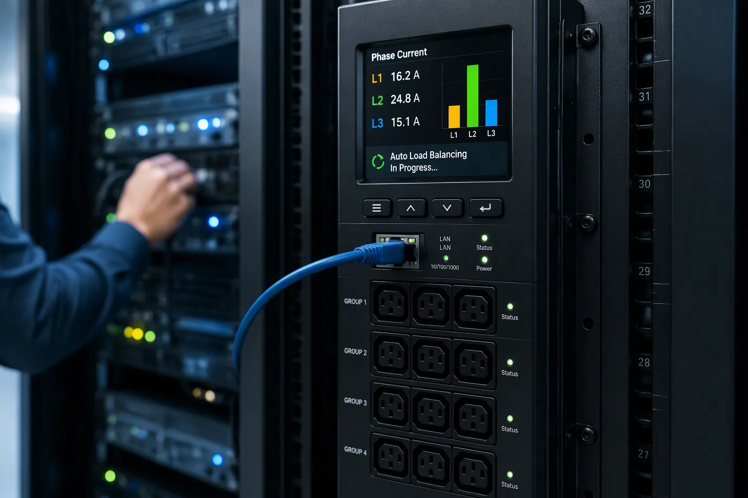
Continuous Phase-Current Monitoring
The unit measures current on every circuit it feeds, not just the total at the input. Per-inlet power sensing tracks current, voltage, power, apparent power, crest factor, reactance, power factor, and accumulated energy for each power circuit. Per-outlet sensing adds device-level current, voltage, power, apparent power, crest factor, and power factor. You read this data through a secure network or serial connection, or through an integral web interface. The controller samples these values at short intervals, so a rising current never goes unnoticed. Every metric updates in real time, so you see the full picture of each circuit.
Monitoring depth separates PDU classes:
PDU Type | Power Metrics | Network Management |
|---|---|---|
Basic PDU | None | No |
Metered PDU | Aggregate current/load at unit level | No |
Monitored PDU | Per-phase or aggregate voltage, current, power (kVA/kW) | Yes (read-only) |
Switched / Smart PDU | Detailed per-phase and per-outlet metrics | Yes (read/write) via SNMP, HTTP, SSH |
Configurable alert thresholds turn this load monitoring into early warning. You set a current draw above 80% of rated capacity, a voltage sag below acceptable limits, a temperature above ASHRAE-recommended ranges, or a power factor drop that signals inefficiency. The PDU pushes alerts through SNMP traps (v2/v3 TRAPs and INFORMs), email, SMS, and syslog. Real-time monitoring at inlet, outlet, and circuit-breaker levels lets you catch heavy loads before breakers trip. A threshold at 80% of rated capacity gives you headroom to act before the breaker opens, so you can respond before overloads develop. That early visibility matters because imbalance stays invisible on a rack front panel; only per-circuit data exposes it.
Algorithms and Automatic Adjustments
Automated balancing rests on a microcontroller that reads phase currents and a set of relays that move loads between legs. The controller compares current on each leg and identifies the least-loaded one. Relays then redirect a load to that leg, so no single circuit carries more power than it should. Each relay closes or opens on command from the controller, and the outlet-to-leg mapping updates in the controller's memory. This is dynamic load balancing in practice: the system rebalances as loads change, without a technician on site.
Load-balancing algorithms add a predictive layer. The controller watches trends in per-leg current and shifts power between phases before a threshold is crossed. That predictive shifting helps prevent overloads rather than reacting to them. In three-phase pdus, the same logic corrects the uneven distribution continuously, so the legs stay close to equal current. The controller can also rotate connections between legs over time, so load spreads evenly across the full distribution path.
The contrast with static design is stark. Poor load balancing leaves distribution fixed at installation, and load imbalances grow as equipment changes. Automated balancing adapts to every change. Load balancing in electrical systems has always aimed at even current distribution; the unit executes that goal continuously and automatically, and its balancing decisions repeat on every cycle of the controller. This load balancing runs continuously. You gain a system that treats balancing as an ongoing process rather than a one-time setup task.
Preventing Overload and Correcting Imbalance
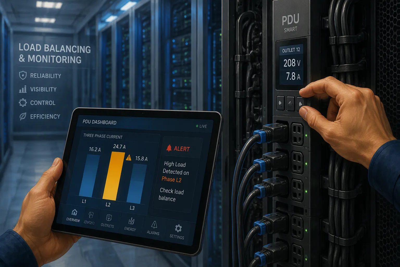
Stopping Single-Phase Overload
Prevention starts with visibility. A smart pdu tracks current at the line, branch, and outlet levels, so you can spot a high-power point before it becomes a trip. Outlet-level metering reports voltage, frequency, and load in real time, and configurable alerts notify staff when a circuit approaches its limit. Set safe capacity thresholds and hold to them: keep usage below 80% of rated current, or below 40% where backup power exists. That headroom protects every circuit from carrying more power than it should.
The operating sequence follows a clear order:
Distribute equipment evenly across all outlets and circuits.
Use real-time monitoring to watch loads as they change.
Relocate equipment when a circuit runs hot.
Avoid clustering multiple high-power devices together.
Periodically verify power usage is even and shift loads if needed.
Inspect circuit breakers regularly.
Manage cabling to prevent overheating.
Automatic redistribution and rotating connections between phases reinforce these habits. The controller moves a load to a cooler leg, and no single circuit absorbs the full burden. This is preventing overloads by design rather than by luck. Poor load balancing hides until a breaker opens; automated balancing acts first.
PDU problems cause 52% of data center outages, underscoring the risk of ignoring load balance.
Correcting Imbalance in Real Time
Correction is where dynamic load balancing earns its name. The controller compares current on each leg and shifts loads to the least-loaded phase. Current unbalance falls, losses drop, and voltage stability improves. Unbalanced currents and voltages shrink toward equal distribution, and the system imbalance that once stressed the transformer fades. Voltage unbalance stays within tight bounds because the legs now share the work evenly.
The correction runs without manual intervention. You do not dispatch a technician or re-patch a rack. The unit rebalances on its own, cycle after cycle, and load imbalances that would otherwise grow as equipment changes get absorbed automatically. Single-phase equipment added to one leg triggers a compensating shift on another. This continuous balancing keeps the distribution path healthy and extends transformer life.
The payoff is a system that prevents overloads and corrects imbalance at the same time. Balancing becomes an ongoing process, not a one-time setup task. You gain reliability, lower losses, and better capacity utilization from the same automated behavior.
Benefits and ESTEL Smart PDU Implementation
Reliability and Efficiency Gains
Balanced loading pays you back on several fronts at once. Circuit stress falls, overload trips become rare, and line losses drop as current spreads evenly across all three phases. Voltage unbalance shrinks, so connected equipment sees a steadier supply. Transformer life extends because every period of elevated temperature adds to cumulative insulation aging; persistent hot spots accelerate insulation degradation, and chronic overload can shorten transformer life. Fewer overloads also mean lower electromagnetic forces on windings, which preserves mechanical integrity.
The efficiency case is measurable. Unbalanced loads drive higher currents between transformer legs, producing waste heat; correcting that imbalance lowers the heat and cuts cooling load in air-conditioned spaces. Better capacity utilization follows, because you reclaim headroom you did not know you had.
Deploying ESTEL Smart Power Distribution Units
The ESTEL Smart Power Distribution Unit fits these deployments well. It supports remote management and an LCD for real-time monitoring, adds surge protection and a dehumidifying function, and comes in configurations from 8 to 19 outlets with a maximum input current of 16A. Its robust build suits industrial environments, and its automated balancing prevents circuit overloads that cause unexpected shutdowns.
Plan the rollout in three steps. First, set alert thresholds below rated capacity so load monitoring warns you early. Second, map every outlet to its phase and physical rack position, so a hot circuit points to the exact device. Third, verify balancing across redundant PDUs by testing a single-source failure and confirming the survivor stays within limits. Treat this smart PDU as one suitable option among others, and confirm it reports outlet-level data your monitoring platform accepts.
Continuous monitoring and dynamic redistribution stop single-phase overloads and phase imbalance before they become failures. Your smart PDU watches current on every phase, then shifts loads to the least-loaded leg. That balancing keeps circuits cool and transformers healthy. The payoff shows up as reliability, efficiency, and reclaimed capacity. You can prevent overloads without manual intervention, and load imbalances never grow into outages. Evaluate your options against standards such as ISO9001, UL, and CE, then confirm each unit supports real-time load balancing. ESTEL's Smart Power Distribution Unit offers one suitable path for your deployment.
FAQ
How does a smart PDU detect a single-phase overload before the breaker trips?
The controller samples per-phase current continuously and compares each reading against your configured threshold. Set that threshold below rated capacity, and the unit alerts you through SNMP traps, email, or syslog while headroom remains. You then relocate the load before the breaker opens.
Can automated balancing correct an imbalance without a technician on site?
Yes. The microcontroller identifies the least-loaded leg and signals relays to move loads there. Correction runs cycle after cycle, so an imbalance never grows into a failure. You gain continuous balancing without dispatching staff or re-patching a rack.
What role does real-time monitoring play in preventing overloads?
Per-inlet and per-outlet metering exposes current, voltage, and power as they change. That visibility lets you spot a hot circuit early and act on it. Without this data, overloads stay invisible until a breaker trips.
How do I verify balancing across redundant PDUs?
Test a single-source failure and confirm the surviving unit stays within its limits. Map every outlet to its phase and rack position first, so a hot circuit points to the exact device. Then check that voltage unbalance stays tight under the full load.
Which specifications should I confirm before choosing a smart PDU?
Confirm the unit reports outlet-level data your monitoring platform accepts, and check its input current rating against your load. The ESTEL Smart Power Distribution Unit offers 16A maximum input, 8 to 19 outlet configurations, and remote management for these deployments.
See Also
Understanding ESTEL PDUs And Their Function In Data Center Cabinets
Methods To Guarantee Reliable Power Supply For Telecom Cabinets
Key Information Regarding Telecom Power Supply Features
ESTEL's Complete Guide For Risk Analysis Of Telecom Cabinet Batteries
Calculation Methods For Telecom Cabinet Power Systems And Telecom Batteries
CALL US DIRECTLY
86-13752765943
3A-8, SHUIWAN 1979 SQUARE (PHASE II), NO.111, TAIZI ROAD,SHUIWAN COMMUNITY, ZHAOSHANG STREET, NANSHAN DISTRICT, SHENZHEN, GUANGDONG, CHINA
