How Infrared Temperature Measurement Enables Cable Overheating Early Warning in Smart PDUs for Telecom Cabinets

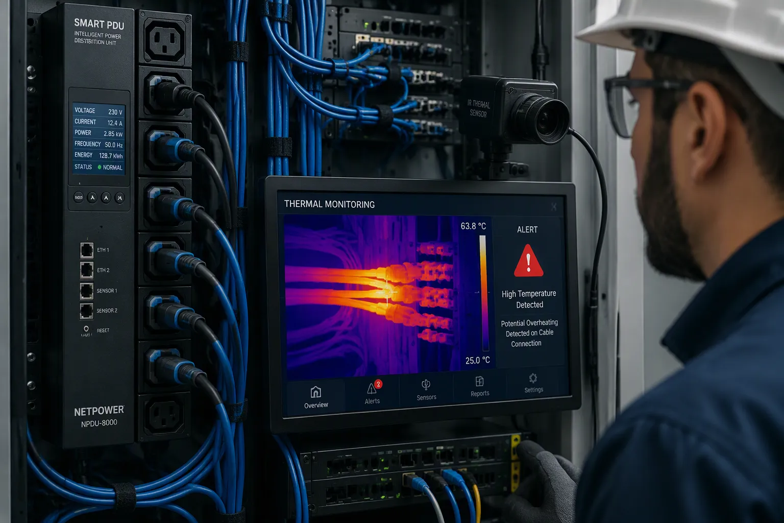
Infrared temperature measurement enables early warning by continuously and non-invasively monitoring cable surface temperatures. It flags anomalies before insulation degradation or failure occurs. Cable overheating ranks among the leading causes of failures and safety incidents in telecom cabinets. Traditional monitoring methods react too late, often after damage has already begun.
You will learn the principle behind infrared sensing, its benefits, and its practical implementation in smart PDUs. ESTEL's Smart Power Distribution Unit incorporates this capability for telecom cabinet deployments. The unit combines infrared thermal monitoring with remote management and surge protection. This combination supports reliable power distribution in demanding outdoor sites.
Key Takeaways
Infrared sensors detect cable heat without touching live parts, keeping workers safe.
Continuous monitoring catches overheating early, preventing insulation damage and failures.
Smart PDUs with infrared sensing reduce downtime and maintenance costs through real-time alerts.
Set temperature alerts below breaker limits and test them under load for reliable warning.
Choose PDUs with proper temperature ratings and outlet configurations for your cabinet's needs.
Cable Overheating in Telecom Cabinets
Common Causes of Overheating
Overheating in a telecom cabinet rarely comes from a single source. You will find four main drivers at work. Each one leaves telltale signs, and each one gets worse if you ignore it.
Loose or corroded connections raise electrical resistance at terminal blocks, lugs, fuse holders, and connector interfaces. Vibration, poor torque, thermal cycling, corrosion, and maintenance neglect all contribute. These cable termination faults create localized hot spots. Those spots can spread to insulation over time.
Overloaded circuits supply more power than the design allows. Higher current flow raises conductor temperature in busbars, rectifiers, and distribution devices. The branch circuit breaker and cabling set the current limit, and any mismatch invites trouble. Aging insulation and components add internal resistance and reduce efficiency. Capacitors dry out, fans slow, connectors loosen, and semiconductors degrade. Blocked vents, dusty filters, poor component placement, and fan failure trap heat inside the cabinet. High temperatures outdoors make heat buildup worse.
Limits of Traditional Monitoring
Contact-based sensors and single-point probes give you a partial picture at best. They measure one location, so a hot spot at a distant terminal can go unnoticed. Localized heating often starts at a single loose joint. A sensor mounted elsewhere will not see it. A single probe cannot cover a row of terminals or a full distribution strip. You get a reading from one spot, not a map of the whole cabinet.
These methods also react after damage begins. By the time a contact sensor registers a rise in temperature, insulation may already be degrading. Periodic handheld checks leave long gaps between inspections. A fault can develop and escalate within those gaps. That delay turns a minor repair into an emergency call. Continuous monitoring across the full conductor run gives you a far better view than a snapshot of one point.
How Smart PDU Thermal Monitoring Works
Non-Contact Infrared Sensing
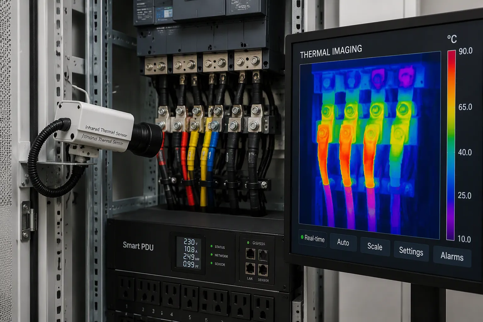
Every object emits infrared radiation in proportion to its heat. Overheated joints and terminations emit more of it than healthy ones. A non-contact sensor captures that radiation without touching the equipment. The sensor converts the captured energy into a thermal image, called a thermogram. Temperature differences then appear as colors: blue and purple for cooler areas, green and yellow for normal conditions, orange, red, and white for hot spots. Loose connections, high-resistance joints, overloads, and deteriorating insulation all show up as warmer colors. This reveals the fault before failure. You judge severity by the heat difference relative to a reference component or to ambient conditions.
Attribute | Detail |
|---|---|
Sensing method | Detects radiant heat signatures without physical contact |
Targeting | Sensors aimed at cable terminations and switchgear parts |
Integration | Linked to central alarm systems for trending |
Coverage | Broad area coverage with a single sensor or camera |
Benefit | Maintains visibility between scheduled inspections |
This approach is the essence of infrared thermography. Thermal imaging turns invisible heat into a readable picture. A smart pdu can aim sensors at designated components and link them to central alarm systems. One sensor or camera covers a large switchgear lineup, a motor control center, or a transformer room. You keep visibility into critical parts between scheduled inspections.
Real-Time Thermal Monitoring
Continuous, full-cable temperature measurement beats single-point monitoring. A single probe reads one location. A hot spot at a distant terminal can escape it. Full-cable coverage tracks the whole conductor run around the clock, so a developing fault cannot hide. Real-time thermal monitoring closes that gap. The system watches every monitoring point, day and night, and compares each reading against its threshold. You get a full picture instead of a snapshot of one spot.
When a monitoring point rises abnormally, the pdu responds through multiple channels. A thermal alert fires the moment a reading crosses its threshold.
Intelligent pdus monitor power parameters in real time. They trigger dual alarms—local audible and visual alerts plus remote email or SMS—to alert administrators for timely intervention.
Panel indicators, LCD displays, and color-coded status LEDs show normal, warning, and critical conditions at a glance. Audible alarms include silence acknowledgment, so operators stay aware even when nobody watches the display. These automated alerts turn a silent fault into a visible event.
Environmental sensors complete the picture. PDUs support external sensors that let you remotely monitor temperature and humidity. You can set environment thresholds and act before a system failure occurs. A sensor with dual inputs supports included 3 ft (0.9 m) and 6 ft (1.8 m) probes, so you can monitor the top, middle, and bottom of a rack. You can deploy an unlimited number of monitors, and each one combines precise dew point measurement with up to 6 distinct measurement points. Together they build a 3D map of heat and humidity distribution inside the cabinet. That granular view beats a single room-level reading. Best practices recommend following ASHRAE standards. Relative humidity should stay between 40% and 60%—too low builds electrostatic discharge, too high causes corrosion. This combination of thermal warning and environmental data supports overall cabinet health.
Thermal Monitoring for UPS and PDU Health
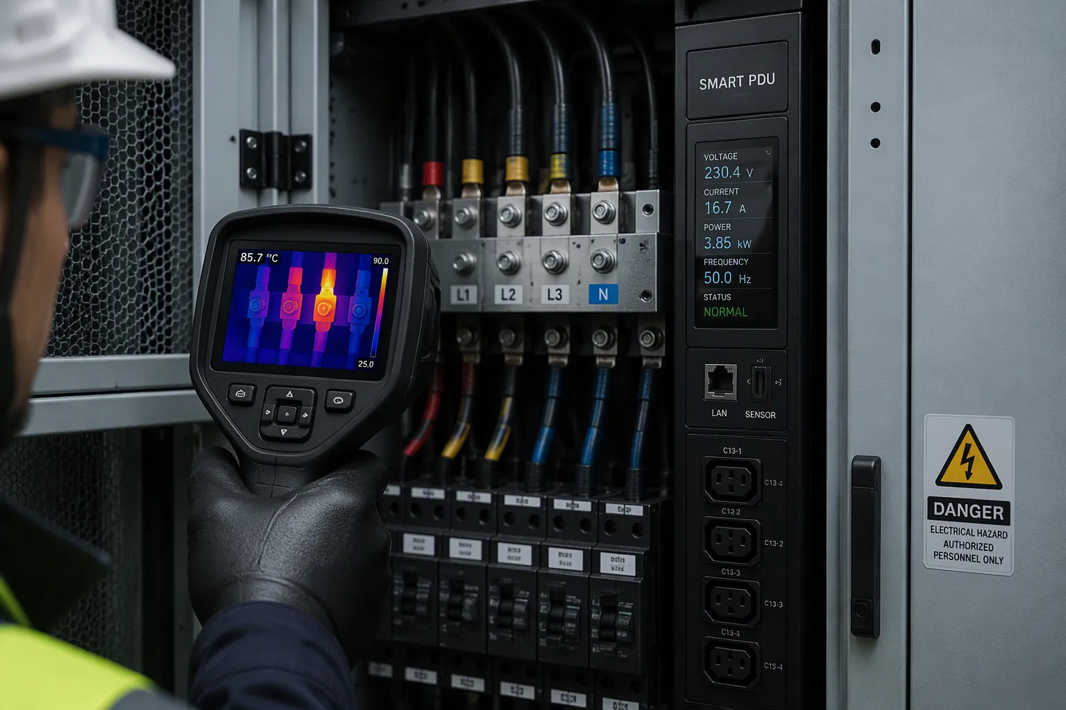
Thermal monitoring for ups and pdu health starts with one goal: catch a fault while it is still small. A rising conductor temperature signals resistance building at a joint or a circuit running past its design limit. Left alone, that heat degrades insulation, and degraded insulation fails. In a high-voltage environment, a failure can arc, ignite nearby materials, or take down the whole cabinet. Early detection prevents overheating from reaching that point. The system sees the trend and acts before damage begins.
Early Fault Detection and Safety
Insulation damage follows a predictable path. Heat softens the material, moisture and contaminants attack it, and its dielectric strength drops. A thermal monitoring system watches the surface heat of cables and terminations continuously. It compares each reading against a threshold and raises alerts when a point climbs abnormally. That signal arrives while the joint is still serviceable. You schedule a repair instead of responding to an outage.
Thermal imaging adds a second layer of safety. A camera or sensor array maps heat across pdu cabinets without contact, so you never open a live panel to check a connection. You see the hot spot on a display and send a technician with the right part. This practice keeps people away from energized conductors. It also catches faults that a single probe would miss. High temperatures at one lug, for example, show up clearly even when the rest of the strip runs cool. A thermal warning fires the moment a reading crosses its limit. Multi-level alarms separate a mild rise from a critical condition, so your team responds in proportion to the risk. Together these measures protect both ups and pdu health and the people who service them.
Maintenance and Compliance Gains
Condition-based servicing changes the maintenance model. Sensors report internal heat, door status, humidity, fan operation, and power conditions, and technicians gain remote visibility into each enclosure. They spot problems before those problems become failures. That cuts downtime and the need for emergency call-outs. Early intervention also stops heat-related damage from progressing, so equipment lasts longer. A pdu that reports its own condition turns a reactive repair cycle into a planned one.
Mechanism | How it works | Effect on emergency repairs | Effect on equipment lifespan |
|---|---|---|---|
Condition-based servicing via sensors | Enclosures report internal thermal readings, door status, humidity, fan operation, and power conditions, giving technicians remote visibility | Technicians spot problems before they become failures, cutting downtime and the need for emergency call-outs | Early intervention prevents heat-related damage from progressing |
Thermal-conscious enclosure design | Purpose-built thermal infrastructure controls heat, a major threat to telecom networks | Fewer service calls and lower outage-related losses | Prevents failures, extends equipment life, and improves uptime; also supports longer battery life and easier maintenance planning |
Compliance support follows the same logic. Documented heat records and alarm logs give you evidence for audits and internal standards reviews. Multi-level alarm systems serve data center cabinets, PDUs, and UPS equipment alike. Handheld thermography still fits periodic surveys, and fixed sensors fit continuous coverage. Each approach has a place, and the best programs combine them. Two pdus in one cabinet can share a single alarm path, which simplifies reporting.
Implementation and PDU Temperature Rating
Comparing Monitoring Options
Each monitoring method fits a different job. Handheld thermal imaging suits periodic surveys and troubleshooting visits. A technician walks the aisle, scans terminations, and records a snapshot of conditions. Fixed infrared sensors suit continuous coverage. They watch the same points around the clock and raise alerts the moment a reading drifts. Thermal cameras cover wide areas and give you a full picture of a switchgear lineup or a rack row. Infrared thermography works best when you match the tool to the task. Many programs pair a handheld survey with fixed sensors for daily watch.
For cabinet-level monitoring, fixed sensors integrated into a smart pdu give you the strongest continuous view. They need no operator present, and they track every monitoring point against its threshold. That constant watch catches a developing fault between inspections.
Choosing the Right Temperature Rating
Start with the load. Confirm the total cabinet load before installation and leave practical capacity for expansion. Then match the unit to cabinet size, load profile, and outlet layout. Ask for tested accuracy, operating temperature, input protection, and outlet limits. PDU maximum operating temperatures vary by manufacturer, typically from 45°C to 65°C. In hot rooms, choose higher temperature ratings to preserve reliability.
Set temperature thresholds below breaker or environmental limits, never at them. Test each alert with a controlled load. Keep sensor locations consistent across racks so readings stay comparable. ESTEL's unit supports this planning directly.
Specification | Detail |
|---|---|
16A maximum input | |
Outlet configurations | 8–19 outlets |
Plug compliance | IEC60309-compliant plug |
Display | LCD display for real-time monitoring |
Built-in dehumidifying function |
The LCD display supports real-time checks, and the dehumidifying function protects the cabinet interior. Review your pdu temperature rating against density and ambient conditions before you deploy.
ESTEL Smart Power Distribution Unit in Practice
Telecom Cabinet Deployment
Consider an outdoor telecom cabinet on a remote roadside site. The cabinet runs base station equipment through a smart pdu with integrated infrared thermal monitoring. Sensors watch cable terminations and distribution strips without touching live conductors. The unit handles a 16A maximum input and offers outlet configurations from 8 to 19 positions. An IEC60309-compliant plug connects the incoming feed, and the LCD display shows conditions at the cabinet face.
The build suits harsh outdoor conditions. Surge protection guards connected equipment against voltage spikes. A dehumidifying function keeps interior moisture in check, which protects insulation and terminals alike. Remote management lets your team check status and adjust settings from a distance. You gain visibility into the cabinet without sending a technician to the site.
Results and Operational Impact
Operators report measurable gains from this setup. Intelligent monitoring tracks temperature and humidity and issues real-time alerts, so your team addresses risks before they escalate. Remote connectivity lets operators troubleshoot the PDU system from anywhere, which cuts response times and on-site visits.
Load balancing spreads power evenly across circuits, which reduces overloads and unexpected shutdowns. Real-time data on power distribution and environmental conditions helps you pinpoint root causes quickly. Thermal imaging and infrared sensing catch a rising joint before insulation degrades. Your cabinet gains earlier fault detection, fewer maintenance trips, improved safety, and stable power distribution. Remote monitoring ties these benefits together in one dashboard.
Infrared temperature measurement in a smart pdu gives you continuous, non-invasive cable monitoring. It catches overheating before insulation fails. A rising joint shows up as heat long before it shows up as a fault. You gain improved safety, fewer maintenance visits, compliance support, and better UPS and PDU health. Each benefit builds on the same early warning signal.
Match your implementation options and temperature rating to cabinet density and monitoring needs. Set alert thresholds below breaker limits, then test each one under load. Fixed sensors in pdus suit continuous coverage best. Explore ESTEL's Smart Power Distribution Unit to bring infrared-based early warning to your telecom cabinets.
FAQ
How does infrared sensing differ from a contact temperature probe?
A contact probe reads one spot and must touch the surface. An infrared sensor reads radiant heat from a distance and covers a wider area. You see hot spots at terminations that a single probe would miss, and you catch them before insulation degrades.
Do the sensors need to touch live conductors?
No. Infrared sensing works without contact, so you never open an energized panel to take a reading. You view the thermal picture on the display and send a technician with the right part. This keeps your team away from live conductors.
What outlet configurations does the ESTEL Smart PDU offer?
The unit comes in configurations from 8 to 19 outlets. It accepts a 16A maximum input and uses an IEC60309-compliant plug. The LCD display shows conditions in real time.
What does the dehumidifying function do for cable health?
Moisture attacks insulation and corrodes terminals, and both raise resistance. The built-in dehumidifying function keeps interior humidity in check. Pair it with environmental sensors and hold relative humidity within the ASHRAE range of 40% to 60%.
How should I set the alert thresholds?
Set each threshold below the breaker or environmental limit, never at it. Test every alert under a controlled load before you rely on it. Keep sensor locations consistent across racks so readings stay comparable, and review thresholds against cabinet density and ambient conditions.
See Also
Maintaining Ideal Temperature Levels for Outdoor Telecom Cabinet Efficiency
Evaluating Cooling Techniques and Their Uses in Telecom Cabinet Systems
Best Practices for Effective Monitoring of Outdoor Telecom Cabinet Performance
Understanding ESTEL PDUs and Their Function in Data Center Cabinets
Strategies for Guaranteeing Consistent Power Supply to Telecom Cabinets
CALL US DIRECTLY
86-13752765943
3A-8, SHUIWAN 1979 SQUARE (PHASE II), NO.111, TAIZI ROAD,SHUIWAN COMMUNITY, ZHAOSHANG STREET, NANSHAN DISTRICT, SHENZHEN, GUANGDONG, CHINA
